You are using an out of date browser. It may not display this or other websites correctly.
You should upgrade or use an alternative browser.
You should upgrade or use an alternative browser.
IMAC Double Build, Carden Pro 124" Extra 300 40%
- Thread starter orthobird
- Start date
-
- Tags
- 40% airplane build thread imac
Notorious B.E.N.
100cc
If you're wanting to try a ZDZ Cam, the 180 has the same mounting dimensions as a DA 170.
scruffmeister
50cc
But the rear-carb will spit all over the lovely new woodwork inside the fusIf you're wanting to try a ZDZ Cam, the 180 has the same mounting dimensions as a DA 170.

Bunky.F.Knuckle
150cc
Velocity stack will cure 95% of that.
Bunky.F.Knuckle
150cc
And the 200 has the same mounting pattern as the 170 and 150.......If you're wanting to try a ZDZ Cam, the 180 has the same mounting dimensions as a DA 170.
Subd'
Sure was good to meet you in your home town and hang out Cam, cant wait to get back again.
Build sure is looking good !
cannot wait til you come back Brian, next time, I am certain our club will not be flooded!
The build continues....
from the manual:
E. Trial fit the Motor Box and Fuse Sides upside down over the Top View Plan.
F. Line up the Motor Box so F-2 matches the Top View Plan. Make sure to position the Motor Box so the Top Plate hangs over the front of your building board so the Box can sit level with the Fuse Sides.
G. Sand the taper on the front and back edge of the Fuse Side to match the Plans.
before E: I rechecked my table top, to assure it is flat. You may not notice, but I replaced the MDF with a new one, that is 1" bigger than the bench top, so now I have more area. Someone asked, what is the size:
here are the dimensions 36" by 86"
I then placed the plans and the plan protector down, and then using my straight edge, I placed the aluminum angles next to it, to make sure everything is straight, then clamped and then screwed down the aluminum angles down to the table over the plan...

aluminum angles getting fixed to the bench top and assuring they are straight also. Cannot trust the plans.

looks straight to me...

then, line up motor box:
Also for Primo, ROLLERMAN my angle on the LE of the truss side with F2....

from the manual:
E. Trial fit the Motor Box and Fuse Sides upside down over the Top View Plan.
F. Line up the Motor Box so F-2 matches the Top View Plan. Make sure to position the Motor Box so the Top Plate hangs over the front of your building board so the Box can sit level with the Fuse Sides.
G. Sand the taper on the front and back edge of the Fuse Side to match the Plans.
before E: I rechecked my table top, to assure it is flat. You may not notice, but I replaced the MDF with a new one, that is 1" bigger than the bench top, so now I have more area. Someone asked, what is the size:
here are the dimensions 36" by 86"
I then placed the plans and the plan protector down, and then using my straight edge, I placed the aluminum angles next to it, to make sure everything is straight, then clamped and then screwed down the aluminum angles down to the table over the plan...
aluminum angles getting fixed to the bench top and assuring they are straight also. Cannot trust the plans.
looks straight to me...
then, line up motor box:
Also for Primo, ROLLERMAN my angle on the LE of the truss side with F2....
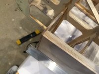
So now, it is starting to come alive:
5. Taper and install F-6 first. Install F-2, F-5, F-4 and F-3 in this order using 5 minute Epoxy.
(F-5 slides in and out and F-4 and F-3 slide fore and aft to adjust for a perfect fit and a straight Fuse Side.)
F6 is at the tail. connects right FS with the left FS.

after you glue F6 1st, then, make sure fuselage sides are square to the plans/ MB
then glue F2 to the front edge of FS/truss (used epoxy).:

then F5, (with epoxy):

after F5, glue in F4 and F3:


here is where I am at now:


I should mention:
Before I began to glue the FS to the MB or F6, I first inserted the wing tube and stab tube phenolic with the CF tubes inside, to help with the alignment. Once they were in, then I began to glue everything together, except, I did not and have yet to glue in the phenolics for the Wing tube or stab tube.
5. Taper and install F-6 first. Install F-2, F-5, F-4 and F-3 in this order using 5 minute Epoxy.
(F-5 slides in and out and F-4 and F-3 slide fore and aft to adjust for a perfect fit and a straight Fuse Side.)
F6 is at the tail. connects right FS with the left FS.
after you glue F6 1st, then, make sure fuselage sides are square to the plans/ MB
then glue F2 to the front edge of FS/truss (used epoxy).:
then F5, (with epoxy):
after F5, glue in F4 and F3:
here is where I am at now:
I should mention:
Before I began to glue the FS to the MB or F6, I first inserted the wing tube and stab tube phenolic with the CF tubes inside, to help with the alignment. Once they were in, then I began to glue everything together, except, I did not and have yet to glue in the phenolics for the Wing tube or stab tube.
Attachments
Thank you sir!
I started on some of the cross bracing.
I will be using hollow carbon fiber rods, only on the top and towards the front, where my hands will be going in and out for battery exchange, etc....
but otherwise, the rest will be stock.
from the manual:
6. Cut and install Cross Braces to the Fuse. (Fuse top side first.) Trial fit the Bottom Deck during this process. The Fuse Side must be straight and square to the building board.
I sued a circular saw, and removed the pilot drill bit, made these plywood discs.
they are then cut down the middle, to make a "half-moon" . These will go on top side and bottom side of the carbon fiber, and I am using epoxy to adhere the whole thing.


I used my 2nd set of plans to cut and measure the cross bracing.

I will be making 4 of each, at each time, one set for each airplane, and one for top and another for bottom.

I still have a long way to go, but it is fun seeing it come together. I can feel it getting more firm as I add the cross braces.
I started on some of the cross bracing.
I will be using hollow carbon fiber rods, only on the top and towards the front, where my hands will be going in and out for battery exchange, etc....
but otherwise, the rest will be stock.
from the manual:
6. Cut and install Cross Braces to the Fuse. (Fuse top side first.) Trial fit the Bottom Deck during this process. The Fuse Side must be straight and square to the building board.
I sued a circular saw, and removed the pilot drill bit, made these plywood discs.
they are then cut down the middle, to make a "half-moon" . These will go on top side and bottom side of the carbon fiber, and I am using epoxy to adhere the whole thing.
I used my 2nd set of plans to cut and measure the cross bracing.
I will be making 4 of each, at each time, one set for each airplane, and one for top and another for bottom.
I still have a long way to go, but it is fun seeing it come together. I can feel it getting more firm as I add the cross braces.