• If you are new to GiantScaleNews.com, please register, introduce yourself, and make yourself at home.

    We're 1st in Giant Scale RC because we've got the best membership on the internet! Take a look around and don't forget to register to get all of the benefits of GSN membership!

    Welcome!
  • Unless you are a paid advertiser NO more posting advertisement in the individual vendor forums. You may post in the Manufacturer's Announcements section only but only ONCE a month unless your a paid advertiser.

Extreme Flight Extra 300 91"

Glued the rudder control horn in place. Since I'm going to use push/pull on the rudder I removed the covering from the servo bay on the back right side of the fuse. I installed four servo screws and screwed them into the wood, removed then and soaked it with thin CA.
 

Attachments

  • rudder servo prep.jpg
    rudder servo prep.jpg
    379.4 KB · Views: 319
  • Rudder control horn.jpg
    Rudder control horn.jpg
    433.2 KB · Views: 351
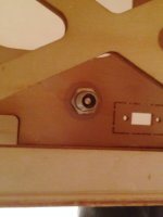
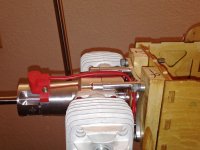
Those of you who installed a DA70 and configured your rudder servo push/pull (at the back of the fuse), I have a few questions:

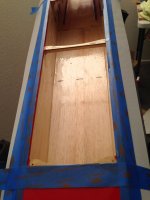
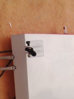
1. Where did you end up mounting your batteries?
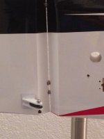
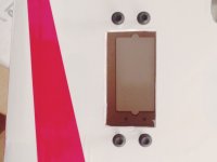
2 Where did you place your battery switches?

I'll have three batteries

1. for the ignition
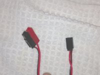
2 Two to power the servos
3. I will need to install 3 battery switches.

I see locations up front next to former 1 for the ignition switches ; however, I don't see any other locations for other switches?

All comments will be helpful.

Thanks a bunch

Chuck

PS HAPPY NEW YEAR
__________________
Scooterpilot
Member of Team Thunder Tiger
Raptor G4, Member of Team YS,
Botos Blades, & Swtich Glow
 
I glued small wood blocks next to the attachment points for the cowl, adding a bit strength. Then I opened up the hole for the rudder using a wood reamer so the knuckles of the hindges would fit nicely without any binding. I rough sanded the robat hinges. Mixed the epoxy and using the stick layed the glue into the hindge holes. I then applied epoxy to the hindges on the rudder, just the last 1/3 of the hindge. I inserted the rudder hindges about 3/4 of the way in and stopped. I used a paper towel to remove any excess epoxy. Then I pushed the rudder into the fuse and set the gap. I used denatured alcohol and cleaned all the hinge knuckles and all along he surface where the rudder and fuse meet. After cleaning I placed a piece of masking tape on top portion of the rudder and let it cure.
 

Attachments

  • Rudder fuse prep.jpg
    Rudder fuse prep.jpg
    568.9 KB · Views: 360
  • Rudder fuse prep 1.jpg
    Rudder fuse prep 1.jpg
    518.1 KB · Views: 346
  • wood block to support canopy .jpg
    wood block to support canopy .jpg
    491.3 KB · Views: 287
  • wood blocks to support canopy attachment points.jpg
    wood blocks to support canopy attachment points.jpg
    519.3 KB · Views: 342
  • rudder hinge gap.jpg
    rudder hinge gap.jpg
    452.6 KB · Views: 305
  • Rudder epoxy curing.jpg
    Rudder epoxy curing.jpg
    668.9 KB · Views: 383
Last edited by a moderator:
Installed the tail wheel. Then I installed the fuel filler. That was easy drill a hole, make sure the covering is cut clean, put thin CA on the wood and install the fuel filler.

I decided to remove the covering over the pipe tunnel. I cut it long so I could iron it back onto the wood in the tunnel. After that I taped the area off with masking tape and mixed up some epoxy mixed with denatured alcohol. I sealed the whole tunned making sure to hit the covering where I had just ironed it to the tunned so it wouldn't come loose if it gets exposed to fuel.

I had to cut all the covering out of pipe vent cover which took time. I iron it and sealed it too.
 

Attachments

  • sealed the exhaust area with epoxy and alcohol 1 1 2014.jpg
    sealed the exhaust area with epoxy and alcohol 1 1 2014.jpg
    731 KB · Views: 352
  • Marked to covering to be cut 1 1 2014.jpg
    Marked to covering to be cut 1 1 2014.jpg
    624.4 KB · Views: 343
  • fuel filler inside fuse 1 1 2014.jpg
    fuel filler inside fuse 1 1 2014.jpg
    755.4 KB · Views: 329
  • fuel filler extrior 1 1 2014.jpg
    fuel filler extrior 1 1 2014.jpg
    540.3 KB · Views: 347
  • cut covering long so it could be ironed 1 1 2014.jpg
    cut covering long so it could be ironed 1 1 2014.jpg
    706.5 KB · Views: 344
  • covering ironed to the pipe tunnel  1 1 2014.jpg
    covering ironed to the pipe tunnel 1 1 2014.jpg
    549.2 KB · Views: 344
  • Tail wheel installed 1 1 2014.jpg
    Tail wheel installed 1 1 2014.jpg
    752.6 KB · Views: 294
  • Under fuse vent 1 1 2014.jpg
    Under fuse vent 1 1 2014.jpg
    790.8 KB · Views: 298
More done tonight. It's actually beginning to look like an Extra. I sealed the hindge gap for the rudder. Then installed the rudder servo and linkage. After that I installed the stabs. I double checked the throw on the stabs to make sure they were even and they were not. I checked this by using two carbon fiber rods and taping one to each of the stabs. As the stabs move up and down you can easily see if the rod stay aligned.

I have low, medium and high rate set up for the stabs and the rudder. Whelp. that's it for tonight.
 

Attachments

  • 1 2 2014 rudder servo installed.jpg
    1 2 2014 rudder servo installed.jpg
    559.4 KB · Views: 406
  • 1 2 2014 rudder servo  linkage installed.jpg
    1 2 2014 rudder servo linkage installed.jpg
    536.6 KB · Views: 465
  • 1 2 2014 stab wiring hole in fuse opened.jpg
    1 2 2014 stab wiring hole in fuse opened.jpg
    420.2 KB · Views: 335
  • 1 2 2014 carbon fiber rods attached to stabs to verify throws are even 1.jpg
    1 2 2014 carbon fiber rods attached to stabs to verify throws are even 1.jpg
    503 KB · Views: 343
  • 1 2 2014 wrapped servo wrire for the stabs and rudder in the fuse.jpg
    1 2 2014 wrapped servo wrire for the stabs and rudder in the fuse.jpg
    543.2 KB · Views: 313
Last edited by a moderator:
I made motor mounts from wood. They are 3/4" thick and should do the job. I did fit check to make sure everything aligned properly and the wood motor mounts fit properly. For once, I won't have to sand they fit perfect.

I also made a JR plug and installed that on the wire DA provided with the motor. This will plug right into the switch, it worked fine.
 

Attachments

  • motor fit check look down.jpg
    motor fit check look down.jpg
    853.2 KB · Views: 386
  • motor fit check.jpg
    motor fit check.jpg
    721.4 KB · Views: 318
  • motor fit check side view.jpg
    motor fit check side view.jpg
    756.8 KB · Views: 350
  • DA extension added JR plug.jpg
    DA extension added JR plug.jpg
    574.5 KB · Views: 319
Top