• If you are new to GiantScaleNews.com, please register, introduce yourself, and make yourself at home.

    We're 1st in Giant Scale RC because we've got the best membership on the internet! Take a look around and don't forget to register to get all of the benefits of GSN membership!

    Welcome!

New ZDZ112 B2RV / Installation into PAU Edge 540

Terryscustom

640cc Uber Pimp
I did not get a lot done today, work took longer and had some business to take care off till late evening. Tomorrow though the weekend is looking much more productive.

So, since this is an engine thread with an airplane build as well, I'm going to dive right into the business end of things. I made a few jigs that I am going to fine tune and when happy will send to Joe to post on his website or wherever in .pdf format to print and use. Anyone that can use .dxf can also PM me and I'll send you files to print or cut for yourself.

So I lasered out a little jig to verify center on firewall in relation to the cowl. This is the circle thing with the long 1/8" drill bit going through this. (I do this with ALL airplanes so this is nothing new, just an updated design I'm testing).

Next I drew up a bolt pattern jig for the firewall based on that previously verified center point. It looks like the 112 is set up for 10-24 mounting bolts which should be more than adequate. Using the bolt pattern as a reference point I drew up a firewall hole pattern template based on the ZDZ drawings on their website.

image002.jpg
 

Attachments

  • image001.jpg
    image001.jpg
    64 KB · Views: 345
  • image003.jpg
    image003.jpg
    57.4 KB · Views: 324
  • image004.jpg
    image004.jpg
    46.7 KB · Views: 359
  • image005.jpg
    image005.jpg
    53.5 KB · Views: 399
  • image006.jpg
    image006.jpg
    59.5 KB · Views: 332
  • image007.jpg
    image007.jpg
    67 KB · Views: 318
  • image008.jpg
    image008.jpg
    62.5 KB · Views: 348
  • image009.jpg
    image009.jpg
    49.5 KB · Views: 337

dhal22

GSN Sponsor Tier 1
Trying to understand here. ALL planes? What about planes that are predrilled? Or is this necessary due to the engine bolt pattern?
 

Terryscustom

640cc Uber Pimp
Trying to understand here. ALL planes? What about planes that are predrilled? Or is this necessary due to the engine bolt pattern?

for pre drilled I'll usually check with the engine but most are not perfect. Safe bet nothing will be pre drilled for a ZDZ though.
 

Terryscustom

640cc Uber Pimp
Well, I had planned for a day off and business dictated otherwise:(. THAT is the sucky part of taking a day off and still being at work.

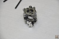
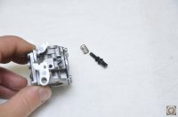
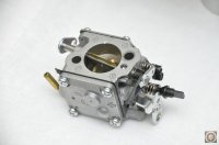
So lets take a look at the carb end of things first. I just want to show this in steps because a lot of people dream up all kinds of ways to mess up a carb. So, I'll just post in steps with the pics in order. The carb is an out-of-the-box carb straight from Walbro so it needs a couple of mods to make it friendly for our use.

1 - 
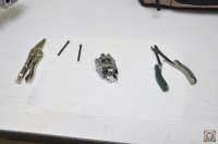
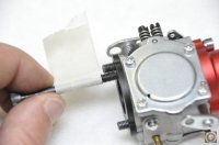
KEEP IT CLEAN! Small dirt makes big problems with carbs. Don't do this in a dirty area, on a dusty bench or anything like that. Use clean tools as well!

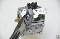
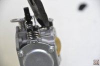
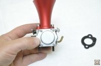
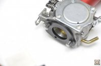
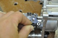
2 - You will notice a plastic arm that locks onto the throttle and pushes the throttle open slightly. This needs to be removed because your throttle servo will bind when you choke it, also you need to have more flexability for throttle setting while choking.

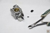
3 - There is a second portion of that plastic arm that is connected to a spring, clip that to disconnect the spring, and you can leave the spring, I chose to pull it off just pinching and pulling with a pliers.

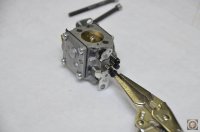
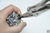
4 - Next we need to remove the factory idle screw for the throttle and deposit it where it belongs. These get a lot of new guy's in trouble and they complain about how fast their airplane lands!! Don't need it. You do need to hold the throttle open to remove this type.

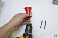
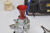
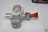
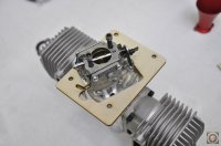
5 - This is not mandatory but I chose to use a velocity stack on mine. I know they don't really add any RPM's but all rear carbs spit at least a little crap out of the carb. I have used stacks on every single I installed down to 20cc and had good results.

6 - This stack came with screws. The holes at the base need to be angled and the screws do not have clearance for the fillet / weld at the base of the cone. I beveled the inside so that it would not rub, it should slide through the carb holes easily.

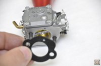
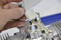
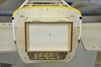
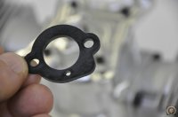
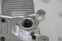
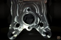
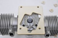
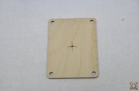
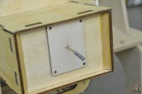
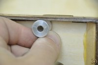
7 - There is the spacer that we talked about earlier that you need to make sure the hole lines up with the hole on the bottom of the carb.

8 - 
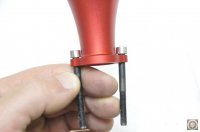
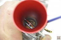
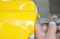
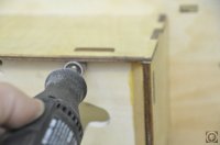
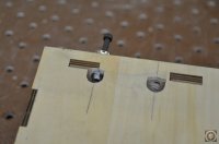
VERY IMPORTANT: The holes the carb bolts into can only be "so" deep because of the rotary valve assembly. What I did was screw in a prop bolt until it just started to snug. I wrapped tape around it and backed it out. This gives me a depth that you are too deep! The bolts sticking out beyond the carb that were supplied with the stack are right there in the "too long" zone. I ground off about 1.5mm off of each and put a slight bevel on the threads. This should be perfect.

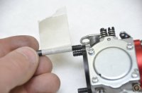
9 - Snug the bolts and check that the choke operates freely. Then tighten the bolts, not muffler tight, but nicely snug. After a couple of runs we will snug these again when the engine is warm because of that plastic spacer.

10 - 
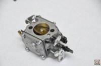
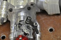
CHECK THE NEEDLE SETTINGS!!!! These engines are run at the factory, it actually smells like gas in the cylinders too. However even from companies like DA, having an engine run and having it tuned are two things. On this carb on any 100-120cc engine the base settings are 1.5L and 1.5H. I usually go just about 1/8 turn more for first starts. This one was a mile off to the rich so I know it was not "tuned". Check them, otherwise you have no idea where you are starting and you will be chasing your tail during tuning!
 

Attachments

  • image001.jpg
    image001.jpg
    53.8 KB · Views: 348
  • image002.jpg
    image002.jpg
    47.8 KB · Views: 353
  • image003.jpg
    image003.jpg
    52.6 KB · Views: 310
  • image004.jpg
    image004.jpg
    53.9 KB · Views: 351
  • image005.jpg
    image005.jpg
    40.8 KB · Views: 344
  • image006.jpg
    image006.jpg
    56.6 KB · Views: 587
  • image007.jpg
    image007.jpg
    57.4 KB · Views: 485
  • image008.jpg
    image008.jpg
    52.9 KB · Views: 512
  • image009.jpg
    image009.jpg
    47.3 KB · Views: 482
  • image010.jpg
    image010.jpg
    114.6 KB · Views: 529
  • image011.jpg
    image011.jpg
    55.8 KB · Views: 533
  • image012.jpg
    image012.jpg
    38.6 KB · Views: 303
  • image013.jpg
    image013.jpg
    50.9 KB · Views: 327
  • image014.jpg
    image014.jpg
    58.8 KB · Views: 321
  • image015.jpg
    image015.jpg
    62.8 KB · Views: 329
  • image016.jpg
    image016.jpg
    53.4 KB · Views: 326
  • image017.jpg
    image017.jpg
    45.8 KB · Views: 324
  • image018.jpg
    image018.jpg
    60.7 KB · Views: 348
  • image019.jpg
    image019.jpg
    56.1 KB · Views: 338
  • image020.jpg
    image020.jpg
    48.8 KB · Views: 342
  • image021.jpg
    image021.jpg
    68.1 KB · Views: 303
  • image022.jpg
    image022.jpg
    62.4 KB · Views: 344
Last edited:

Terryscustom

640cc Uber Pimp
So with all the hubub on the engine out of the way, lets mount this baby.

I drilled a hole at the center point of the engine on the firewall and used my jig to drill the mounting holes. No matter what plane, the top bolts are going to be close to the top of the firewall, so it is handy that I picked this plane as the top of the engine box actually tapers down towards the fuse. That is not a problem, the engine box top can be slightly "adjusted" for bolt access without causing structural issues. After installation we will also be adding a few things to the engine box, stay tuned....

I designed a G-10 push rod for the throttle that is set up for linear throttle movement when the throttle servo is mounted against the inside of the engine box. I do not believe in clipping the spring on the throttle arm so I used a file to recess the bottom of the G-10 arm to not pinch the spring clip. @thelaw was cutting parts so I had her machine it out for me.

image031.jpg
 

Attachments

  • image023.jpg
    image023.jpg
    74.5 KB · Views: 306
  • image024.jpg
    image024.jpg
    44.2 KB · Views: 320
  • image026.jpg
    image026.jpg
    65.2 KB · Views: 364
  • image027.jpg
    image027.jpg
    55.4 KB · Views: 315
  • image028.jpg
    image028.jpg
    41.7 KB · Views: 326
  • image029.jpg
    image029.jpg
    49.5 KB · Views: 314
  • image030.jpg
    image030.jpg
    86.4 KB · Views: 317
  • image032.jpg
    image032.jpg
    67.7 KB · Views: 300
Top