• If you are new to GiantScaleNews.com, please register, introduce yourself, and make yourself at home.

    We're 1st in Giant Scale RC because we've got the best membership on the internet! Take a look around and don't forget to register to get all of the benefits of GSN membership!

    Welcome!

DA 120 with onboard Tach.

IMAC FANATIC

40% happier than most folks.
Thays what I just ordered : pn# evoa 107. I went through 4 pages of Google , and found ONE at new egg . Every other place w buy now button sent me to horizon which said. Discontinued item. Crazy, and makes me wonder why such a cool part would end. When more giant scale guys find out about this set up those are gonna be gold.
 

IMAC FANATIC

40% happier than most folks.
Recieved my part. Evoa 107 , an evolution made interface for telemetry, zero difference using this and our system, im going to fly with as is and if something goes wonky in the readings, ill swap to the factory part.
 
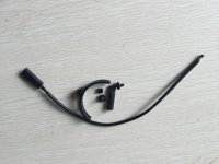
Thanks for this thread @49dimes - super helpful. I've got the sensor shown below on the way to attach to my DA-120. From the picture is looks like I will be able to orient the semi-conductor as necessary to get a reading.

$_12.JPG

I plan to attach the Hall sensor to the Jeti MRPM-AC telemetry sensor (configured as 2-pole motor) rather than a mini-tacho as has been done in this thread so far.

My ignition system uses a separate battery from the radio system for isolation with optical isolation for an ignition kill switch. The new telemetry Hall sensor will be powered from the radio battery to avoid bridging the actual DA ignition unit to the radio via the ignition battery.

I found a diagram (note: offsite link) showing how the sensor can be wired up and supply power to the Hall sensor. But, I have a question ...

Does anyone know the specifications/part number or anything else that could help to identify the exact semi-conductor used in the Rcexl Hall sensors - I need to determine the voltage range it can handle?


My entire radio system operates at a regulated 7.4V which may be too high for some semi-conductors!

Image.png


Thanks
 
Last edited:

49dimes

Damn I'm hungry
Thanks for this thread @49dimes - super helpful. I've got the sensor shown below on the way to attach to my DA-120. From the picture is looks like I will be able to orient the semi-conductor as necessary to get a reading.

View attachment 42165

I plan to attach the Hall sensor to the Jeti MRPM-AC telemetry sensor (configured as 2-pole motor) rather than a mini-tacho as has been done in this thread so far.

My ignition system uses a separate battery from the radio system for isolation with optical isolation for an ignition kill switch. The new telemetry Hall sensor will be powered from the radio battery to avoid bridging the actual DA ignition unit to the radio via the ignition battery.

I found a diagram (note: offsite link) showing how the sensor can be wired up and supply power to the Hall sensor. But, I have a question ...

Does anyone know the specifications/part number or anything else that could help to identify the exact semi-conductor used in the Rcexl Hall sensors - I need to determine the voltage range it can handle?


My entire radio system operates at a regulated 7.4V which may be too high for some semi-conductors!

View attachment 42166

Thanks

I'm pretty sure they can go as high as 24vdc. Nominal is 3-12vdc.
 
Hey guys, so I got my hall sensor - all looks good. What do you recommend for securing the screws that hold the sensor in place so they don't vibrate loose? Normally I would use thread-lock but seem to remember thread-lock and aluminum aren't a good combination?
 

49dimes

Damn I'm hungry
Hey guys, so I got my hall sensor - all looks good. What do you recommend for securing the screws that hold the sensor in place so they don't vibrate loose? Normally I would use thread-lock but seem to remember thread-lock and aluminum aren't a good combination?

Get some plumbers tape and use your exacto #11 to cut a 1/8" wide piece 3" long. Wrap the screw just a couple of times.
 
Top