• If you are new to GiantScaleNews.com, please register, introduce yourself, and make yourself at home.

    We're 1st in Giant Scale RC because we've got the best membership on the internet! Take a look around and don't forget to register to get all of the benefits of GSN membership!

    Welcome!
  • Unless you are a paid advertiser NO more posting advertisement in the individual vendor forums. You may post in the Manufacturer's Announcements section only but only ONCE a month unless your a paid advertiser.

My 3DHS BIGFOOT build

August 14th

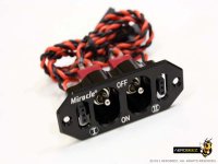
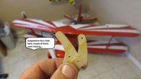
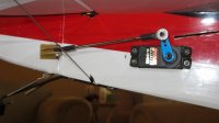
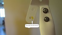
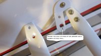
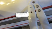
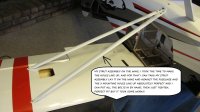
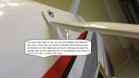
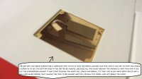
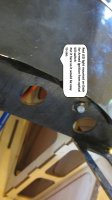
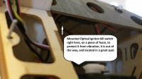
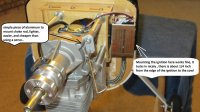
Got a little more done today, I finished up the engine install, made my choke rod bracket, and bent the rod to where it sits in the side opening by the prop shaft. I just used a piece of straight aluminum, drilled a 5mm hole for the mounting bolt, and a 3/32 hole for the rod and mounted it. Next I mounted the ignition, I shortened the the spark plug wire by about 6 inches, that way I did not have to worry about bending, and routing it around stuff, comes straight off the plug up to the box. The location I mounted it in works fine, it can be turned sideways if you wanted to. I installed my optical ignition kill switch under the top of the cowl/fuse , basically behind the dash, that position allows for the wires to be close to everything, and not have to run extensions on all the leads. I used foam, and double sided tape. The kill switch has a RED LED that lets you know when it is armed, I decided I wanted it in the dash, and not on the outside of the fuse, this location allows a quick look to easily see and verify the ignition is armed.
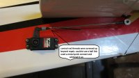
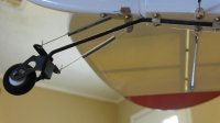
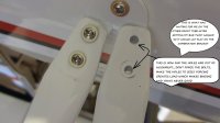
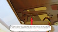
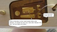
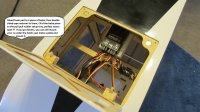
I also installed the reciever, I had this reciever from another plane, its a 9 channel, Even though I fly with a DX-8 I use the higher ch. recievers because they have extra aux satt rx on them, this one has two antennaes on the main reciever, and tow extra satts. I mounted it on the tray that is used for the pull-pull rudder setup ( electric power setup) I like this location as it is right under the roof panel, allowing easy access to the reciever, and thats a good thing because You will be plugging in the ailerons and flaps when you install/remove the wings, its nice to have those connections. ONE THING I did, I do not like using extensions, however sometimes you have to,, I used a Y connector for the flaps, I use a dedicated channel for each aileron, I did use a HD short extension for the ailerons out of the rx,,WHY? becuase I dont believe it is good to constantly be plugging and unplugging connectors into the reciever, I use a short extension and plug into that and then use servo safety clips on that connection.
Thats it for today,,
Getting closer
the Optical kill switch cost me 20$
the 9 channel rx cost me around 130 when I bought it so
current cost of plane
plane 540
engine 270
servos 493
kill switch 20
reciever 130
$1453
 

Attachments

  • IMG_3151.jpg
    IMG_3151.jpg
    156.3 KB · Views: 350
  • IMG_3152.jpg
    IMG_3152.jpg
    72.9 KB · Views: 353
  • IMG_3153.jpg
    IMG_3153.jpg
    117.8 KB · Views: 361
  • IMG_3155.jpg
    IMG_3155.jpg
    154.9 KB · Views: 389
Last edited by a moderator:
August 15th

Bought a prop today, after a lot of thinking, I went with the xoar 20x8 pja prop, due to I have run them on a lot of my planes and like them, they are fairly priced and easily gotten. Also I do not know yet how the plane will fly with this prop, do I don't want to dump money on a Composite prop maybe later though.
I also bought a spinner for the plane, after looking I decided on the miracle from aerobeez, I think it will be a perfect fit, and its nice and light,,
I bought the power switch for the plane also,, I Like the HD miracle switches from aerobeez, I have them in a couple of my planes, I like the way they look, and the HD toggles that are on them, also like having both swtiches and charge ports on one plate.
current cost of plane
plane 540
engine 270
servos 493
kill switch 20
reciever 130
prop 26
spinner/switch 50
$1529
 

Attachments

  • SPR-MC-3D-RD_P_1.jpg
    SPR-MC-3D-RD_P_1.jpg
    50.6 KB · Views: 288
  • SW-MC-J001-BK_P_1-01-02.jpg
    SW-MC-J001-BK_P_1-01-02.jpg
    64.4 KB · Views: 270
Last edited by a moderator:
August 15th

Ok, I think I just purchased the final thing I need to get the plane ready,, BATTERY CHOICE...
for the ignition I am using a 6v 5cell nimh pack that I have and know to be good and hold its capacity, this is fine as the new dle ignitions are rated up to 8 volts, so I don't have to use a regulator, and the battery does not weigh much,
For the flight pack, I ordered a new 2500 mah LIFE a123 battery from hangtime hobbies, I run these batts on all my planes, they hold their power very well and can keep the digital servos happy, They are not as volatile as lipos and just have more power than any other packs I have used,, the 2s life pack is rated at 6.6 volts, I run these packs without regulators on my other planes and have never had an issue.

current cost of plane
plane 540
engine 270
servos 493
kill switch 20
reciever 130
prop 26
spinner/switch 50
ign. battery 30
Life battery 65
$ 1624

I have listed prices so you may know what it cost to build one of these the way I have done it, (AND SO YOU MAY KNOW WHY WE GET PISSED WHEN OFFERED 400 DOLLARS BY FOLKS WANTING TO SNATCH A PLANE UP CHEAP) , there are a few other cost I have not included,, such as epoxy, CA, balsa pieces, double sided tape, foam, screws, ETC,, these are all things that do not come with an arf, but you will need them, most of us who build these already have these supplies,, but if you don't realistically you need to plan on spending another $50-75 for building supplies.
 
Last edited by a moderator:
August 15th

OK, I took a little time to go ahead and hook up the elevator and rudder linkages,, Remember it is always key to set your throws up so you have as much mechanical advantage as possible, I set my throws for 140% and put my linkages where they need to be to accomplish this, I had to use two different servo horns to accomplish this on this plane, but I am happy with it,, there is a good amount of throw in the elevator, wish I had more on the rudder,,
GRIPE TIME: I do not like how close the elevators are to the rudder, You will never be able to get alot of throw from the rudder due to it hitting the elevators, or the horns,, does this plane have enough throw,, It must because I seen Joe smith flying the tar out of it, I am just used to setting up 3d throws on my planes, I always look for the maximum allowable throw.
COMPONENTS: the hardware in this kit is OK, its not super, and its definately not top quality, the ball links are ok, however I had two control rods with screwed up threads so bad the rod end would not screw on, I was able to clean one up, and fix it, the other one I was not able to, I ended up using a quick connect and soldering it in the end of the rod,, I have no worries about the setup, I know it is super strong, it just sucks that the supplied rod is no good. Another issue, some of the composite control horns did not have the holes drilled in them, ONCE AGAIN, its not a show stopper and its an easy fix for me, but it is also not and issue I would expect to have from a 500+ dollar 30cc arf. I expected better.
I already had the tailwheel mounted I hooked up the springs, and its ready, thats all I got done been working alot, Will work on it again tomorrow, getting closer!!
 

Attachments

  • IMG_3160.jpg
    IMG_3160.jpg
    106.7 KB · Views: 364
  • IMG_3161.jpg
    IMG_3161.jpg
    99.1 KB · Views: 358
  • IMG_3162.jpg
    IMG_3162.jpg
    98.5 KB · Views: 356
  • IMG_3164.jpg
    IMG_3164.jpg
    97.6 KB · Views: 336
Last edited by a moderator:
---Wing support tubes INSTALLED !!!!!

Thanks guys, I appreciate it
OK, now on to the wing support tubes, I have had some people ask me about this so I decided I would go ahead and tackle it today,, FIRST OFF LET ME TELL YOU,, if you have some grand illusion of this just falling in place and lining up, forget about it,:crying: its gonna take some time and work to get it right,,the object is to be able to be able to take the assembled wing support assembly and lay it on top of the wing and against the fuselage and have all three bolt holes line up exactly with the holes in the assembly.
NOTE::: The online manual shows the assembly mounting to the fuse and wings with allen head bolts,, my plane did not come with them,:grumpy: it came with PHILLIPS head bolts,the same as the ones used to mount the tubes to the bracket just a little longer, I don't like them, so I swapped to allen head bolts, I already had these bolts, so it was not an issue for me, but it may be for you,,, may mean a trip to the hobby shop to get them, or the hardware store if you are lucky enough to have screws this small...

HERE IS HOW I ACCOMPLISHED IT
Before you even start on the wing support assembly make sure your wings are fully seated against the fuse and the wing bolts are tight!!!
NOW,,,,,,,
--1--First locate the mounting holes, there are two in the wing and one on the fuselage, the two in the wing are not that hard to find as there is a tiny hole in the covering above them to help find them, the ones in the fuse have no such hole, so just look at my pic to get a reference and feel around until you find it. Then remove the covering, I use a pick, that I heat up with a plumbers torch till its glowing, then stick it in the hole and go around the edges, gives me good clean removal of covering. Once you have removed the covering, inspect the hole, and make sure there is nothing in front of the blind nut, I had wood in front of mine due to a bad install, I used my pick again and burned the little bit out, and they are ready.

--2-- Take the combination bracket and install it on the fuse, you want it tight but just snug it, you want it to rotate so you can line up the braces

--3-- LOOK at the braces, one side is flat all the way across, the other has some curves in it,, common sense tells you that the flat surfaces need to be against the mounting bracket, if your mounting tabs are backwards, ALL MINE WERE Take the screw and nut out, flip the tab on the brace and reinstall the nut and screw

--4-- Put a bolt in the mounting tab and install it on the wing and snug it, then lay the tube on the combination bracket, then take the other one and do the same, NOW look at how the braces lay against the bracket first, do they lay flat, if not you may need to remove the comb. bracket and bend it,
:::NOTE:: when I laid the braces against this bracket I notice that it needed to be bent, the tabs were facing to far down, and needed more of a bend, I used a set of wide pliars gripped it and made small bends until I was happy,, I had to do this to both sides

--5--now that you have the tabs in the wings and snug (not too tight you want them to be able to move a little right now) have a look at the holes, ON BOTH MY WINGS the rear braces holes lined up perfect, so what I did was install the hardware and bolt the tube to the bracket not too tight,,

--6-- now have a look at the holes on the front brace,, WHAT YOU ARE GOING TO SEE IS IT NEEDS SOME WORK,, so take small bits at a time, the first thing you will notice is that the brace does not lay well on the bracket, because it is at a forward angle, (the front blind nut is mounted in the contour of the leading edge of the wing, this causes the brace to be at an angle compared to the comb. bracket, SO GET A GOOD LOOK and guess about how much twist you will need, then remove the brace, and use a set of pliars,vise, ETC, whatever you have and get ahold of that tab that mounts to the wing, get a good grip with the pliars, and grab the tube and twist it in the direction it needs to to, (towards the rear of the plane) You are trying to put an actual twist in the the tube, NOT THE MOUNTING TAB that's why you have a hold of it, IT STILL NEEDS TO MOUNT FLAT ON THE WING, it wont take too much twist, but it will take some muscle,, put the brace back on the wing, and the bolt in the tab, once you are happy with the twist, --the tube is laying flat on the comb. bracket, and the mounting tab is flat on the wing, that's when we go to the next step

--7-- You will have a look at how the holes line up, they were off on both of mine, on one side of the plane 1 wing tube only had 1 hole out of alignment,, the other side though was way off,, Lay the tube where it goes on the bracket, and then make a mark on the bracket where the hole should actually be,,,, I used a carbide burr on a die grinder to open the holes up on mine, but a dremel tool with the right bit will do just the same,, Once you have the holes lined up, put the screws in, use a washer if you had to remove metal, then the nut,

--8--OK now tighten the screws holding the tubes to the brackets.
NOW , what you should have is just what I have, I can remove the three support mounting bolts, and lift the support assembly off, ,, then I can set it on the wing, and against the fuse, and all three holes line up perfectly, I can start the bolts by finger,, run them in, then tighten them up and ready to go..
I hoped this helps someone out there just to let them know how this goes together,,

3DHS IF YOU ARE READING THIS
I am a maintenance tech by profession, so I fix things that don't fit or work for a living,, Not all people do,,, In my opinion, the wing support assembly could be made much easier, using the supplied components if you just delivered the combination bracket with only 1 hole in it, the hole for mounting to the fuse,and a simple cheap Jobber drill bit. That would allow the person assembling to install the tubes, and position them in the correct position, lay them on the bracket, mark the holes and drill them, then DONE,, perfect fit,, Just my 2cents
 

Attachments

  • IMG_3170.jpg
    IMG_3170.jpg
    400.2 KB · Views: 347
  • IMG_3172.jpg
    IMG_3172.jpg
    385.7 KB · Views: 331
  • IMG_3173.jpg
    IMG_3173.jpg
    389 KB · Views: 317
  • IMG_3176.jpg
    IMG_3176.jpg
    397.9 KB · Views: 332
  • IMG_3177.jpg
    IMG_3177.jpg
    390.4 KB · Views: 308
  • IMG_3179.jpg
    IMG_3179.jpg
    395.8 KB · Views: 312
  • IMG_3182.jpg
    IMG_3182.jpg
    382 KB · Views: 312
  • IMG_3184.jpg
    IMG_3184.jpg
    391.6 KB · Views: 313
  • IMG_3183.jpg
    IMG_3183.jpg
    391.9 KB · Views: 301
  • IMG_3189.jpg
    IMG_3189.jpg
    394.5 KB · Views: 297
  • IMG_3191.jpg
    IMG_3191.jpg
    411 KB · Views: 369
  • IMG_3185.jpg
    IMG_3185.jpg
    399.3 KB · Views: 318
Last edited by a moderator:

gyro

GSN Contributor
Awesome detailed info, thanks for sharing your experiences and suggestions Ronnie.
 
wing servos

Thanks Gyro,, hopefully this build will help some guys so they know what to expect and ways to help with their build,,,
 
OK, first off the way the aileron servos mount in the wing SUX,,,the lower two holes of the servo are very difficult to get in, You have to try and put them in at an angle, and then try to get them screwed in, but if you lean your screwdriver over against the wing, the wood is so thin it will crack and break,,
After seeing the issue, I decided I would first put the screws in without the servo, that way the threads would be cut and I could put some thin CA in the holes before mounting the servo,, EVEN THIS PROVED TO BE A PROBLEM,,the top holes are not bad, you can get the screws in, the lowers are the problem child,,, I started the screw, of course you have to push on it to get it to bite into the wood,, and about halfway thru the mounting plate the wood split in 1/2,,, WHAT A BUNCH OF CRAP!!,, I removed the screw, and then put some CA on the wood and glued it back together. THIS IS NOT WHAT I EXPECTED from my
3dhs plane,, maybe its me, but this is my first plane from them, and it has had its issues, I have had far less expensive kits with none of these problems, so It does get my temper up, but hey, things happen so keep chuggin at it.
My best solution for the aileron servos is to use allen head servo screws, that way I can use a ball head allen driver, which will allow me to get the angle I need to put them in, and not push on the wing. I dont have any of these so that means a trip to the hobby shop.. SO thats it for the aileron servos for tonight.

-Moving on to the flap servos,,these installed pretty easy, just a little fishing to get them in the holes, and put the screws in, no problem with them as you can use a long phillips screwdriver and get them in easily,,, I DID however have to use a file to open up one of the servo bays a little, it was just a hair too tight, and the servo would not push in, a little filing and it went in.
SO today after work, I will go to the hobby shop and get the screws I need, install the aileron servos, then mount my control arms and set my linkage and throws.
 

Attachments

  • IMG_3169.jpg
    IMG_3169.jpg
    395.8 KB · Views: 320
  • IMG_3167.jpg
    IMG_3167.jpg
    396.8 KB · Views: 329
  • IMG_3168.jpg
    IMG_3168.jpg
    394.6 KB · Views: 332
Top