• If you are new to GiantScaleNews.com, please register, introduce yourself, and make yourself at home.

    We're 1st in Giant Scale RC because we've got the best membership on the internet! Take a look around and don't forget to register to get all of the benefits of GSN membership!

    Welcome!

Airplane Design Fusion 360

BalsaDust

Moderator
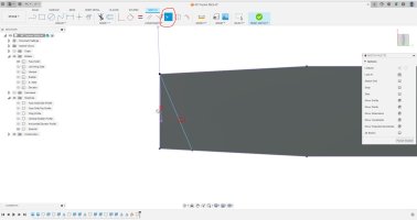
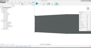
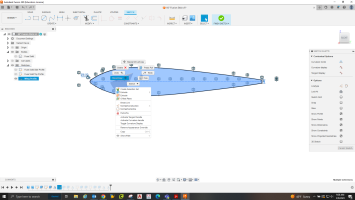
Now I will sketch the top profile of the fuse onto the solid. The rear taper appears to be slighlty curved so I will use the 3 point arc command to draw it.
Fuse Solid7.png


You can see the start and end points of the arc and in the middle will be the fit point for it that defines the radius of the arc. Afterwards I also traced the front tape with just a straight line but it is currently not pictured. again click finish sketch.
Fuse Solid8.png


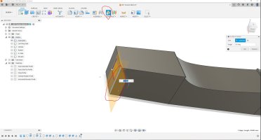
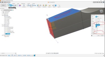
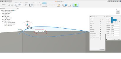
Click the extrude button. This time since there are multiple profiles at play you will need to select which ones you want to extrude. You can see that it defaults to an up arrow wanting to extrude out and away from the face.
Fuse Solid9.png


I forgot to take a screen shot here but in the extrude tab I selected "To Object" under the extent type tab. with that I don't need to type in a distance. Instead I roll over my view and select the top of the fuse where the wing will ultimately rest. It should automatically change the operation from new body to "Cut" but if not change that now and click ok. This will cut away material leaving you with the top profile.
Fuse Solid10.png


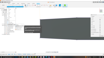
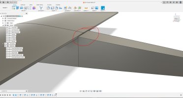
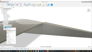
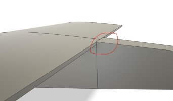
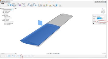
Next in the create tab drop down click on the "Mirror" tool. Its control box will pop up and you will see the objects tab highlighted telling you to select all solid bodies you want to mirror. There currently is only one so go ahead and click on it to highlight the entire fuse half.
Fuse Solid11.png


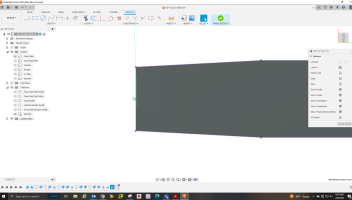
once everything needed is selected you will need to click on the mirror plane box, this will allow you to pick which way it mirrors. Just click on the appropriate face and you will see a preview of how it wants to mirror it. Also for the fuse down in the operation tab I will just leave it as the defaulted join operation. If I was say mirroring the wing I will instead change it to new body so each wing half was a separate part.
Fuse Solid12.png
 

BalsaDust

Moderator
A few things to note that I haven't mentioned yet.

In the browser to the left there is an eyeball image. If you click on it it turns on and off the visibility of that feature. This will get used a lot.

Also note the expand arrows. Opening these up will show everything within that folder. It's a good idea to go ahead now and start re-naming everything. you will hate yourself if you don't once you have a bunch of the structure modeled in. Currently this model if I expanded the sketch tab it would show top sketches and they would be named sketch 1 and sketch 2. I will re-name them Fuse Solid Side Profile and Fuse Solid Top Profile. You will also want to start naming the solid bodies.

When extruding a sketch you can extrude from that sketch many different times if you would like and there is a good chance you will. But after drawing a sketch the first time you extrude a part the visibility will automatically turn itself off. This is where re-naming everything comes in handy.
 

BalsaDust

Moderator
Got a lot done this evening and will take time during my breaks at work tomorrow to post the steps getting this far. Takes quite a bit more time to take screen shots of it all as I go. I guess the easier approach would be to video it all in sections and I may do that for some parts.


Screenshot (60).png
 

BalsaDust

Moderator
Ok lets start the wing. First I want to again start a sketch on the middle workplane. In the image below I have projected just that single top surface onto my sketch. Note over on the sketch palette a line type option is highlighted. I selected it and projected that top surface as a construction line. (Construction lines give you the geometry and something to dimension off of but will not sure up when you extrude items. I use them alot.) also note I have drawn a 8mm dia circle at the LE to give me the radius there. there is also a single 2.5mm vertical line at the TE.
Wing1.png


Now I use the fit point spline tool to trace just the top profile of the wing. You can use as many fit points as you would like but I have found in general you want to use as few as possible to achieve the desired shape. Note at the LE a constraint there that is a line and a circle. That is the tangent constraint. I used it to make the radius of the wing profile flow smoothly into the radius of the LE circle.
At this point go ahead and use the mirror tool. Select the upper profile and the TE line, then click mirror line and use that construction line from earlier.
Wing2.png


Now to clean it up a bit before going any further. on the modify tab click the scissors which is the trim tool. Go to the LE circle and trim away the inside portion of it. when you hover over a line to trim it will highlight in red how much will trim away.
Wing3.png


Because of that construction line you will have to trim the top and bottom but it should look like this.
Wing4.png
 

BalsaDust

Moderator
Now you can finish the sketch and start to extrude. for the first action we will select the rib profile, use "symmetric" as the direction, "all" as the extent type, and "cut" as the operation. This will cut through everything currently visible in the path.
Wing5.png


Now we have a nice wing saddle cut into the fuse so lets extrude the wing. First go ahead and go into the sketch browser and turn the wing profile sketch back on.
Wing6.png


Now we can extrude it again going to one side and as a new body. I'm going for a 60" span airframe so one wing panel will be 30" which is technically 762mm. I'm figuring the wing tip on this will be about 2" so I'm extruding it out 711mm which is roughly 28mm.
Wing7.png


After that is done I go ahead and mirror the wing like we have done previously but I select new body as I want each wing half to be separate.
Wing8.png
 

BalsaDust

Moderator
Now onto the vertical stab. I went ahead and projected the top and rear profiles of the fuse. I did them as construction lines but it really doesn't matter for this one.
Vertical1.png


Next I first use the line tool draw the bottom of the vertical which will stay right on the projected line since I did it as a construction line as well as draw what will be the hinge line. Then I use the fit point spline again to trace the outline of the stab and rudder.
Vertical2.png


Notice that after done drawing the lines I can click and highlight the vertical and rudder independently of one another. If you can't do this then you wont be able to extrude as it can't see all the geometry to extrude.


Vertical3.png

I have not shown it here but the sketch is complete so go ahead and extrude the vertical and rudder as two different bodies. This again will require doing one of them first, then going and turning that sketch back on to do it again. This workplane was on the centerline of the fuse so be sure to extrude using symmetric. I did 3mm which will go 3mm both ways making the parts 6mm thick which is basically 1/4"
 

BalsaDust

Moderator
Now for the Horizontal stab and elevator. Lets sketch on the bottom of the fuse solid and project that outline using construction lines.
Horizontal1.png


Now start sketching the outline with the line tool. We are only drawing half of the stab so when you select the line tool go hover over the projected line of the rear of the fuse. If you are close enough a little triangle should pop up which is a center of line constraint and it will snap to it.
Horizontal2.png


From that center point work your way forward and around the profile. One thing to note for those with previous AutoCAD experience. If a line isn't exactly in the right spot just click the point and drag it where you want. everything that is connected to it will go with it unlike in CAD where you have to select it all. Another thing to note. Modeling software is very easy to make changes at a later time including dimensions of things unlike AutoCAD where you pretty much need to dimension as you go.
Horizontal3.png


Here I'm going to the modify tab to select the fillet tool.
Horizontal4.png


I apply a fillet to both corners. For me a 8mm radius looked about right. with this tool you can either select both lines to fillet or if you hover over the point where they connect it will allow you to click there as well.
Horizontal5.png
 

BalsaDust

Moderator
Now lets extrude one half of each part.
Horizontal6.png


Note in the previous picture the arrow wanted to extrude down so I had to type in -6 to go up. Also note in this picture since it sees the fuse there as soon as I change it to a negative number it auto changes the operation to cut.
Horizontal7.png


For this I do not want to cut this notch in the fuse just yet so lets change it to new body.
Horizontal8.png


Now lets do the same thing for the elevator. this time m extent type will be to object and I will go to the top of the stab. Also still keeping it on new body.
Horizontal9.png


After this go ahead and mirror both the elevator and stab. First turn the fuse and elevator solid body off. Mirror the stab and tell it to join. Then turn the stab off and the elevator back on and do the same thing. It has to be done this was as when you tell it to join it will join into one solid body with any other solid it touches. So if you left the fuse on when mirroring the stab that would become one piece.

Also note I did not draw the scallops on the elevator. If anyone decides to build from this design they are welcome to add them but I'm not a fan so I will be leaving them off.
 

BalsaDust

Moderator
Ok first I think I'm going to stop inserting full images as I feel it's cluttering things up. If yall would prefer I still do just let me know and I will change back. Lets now address an item I forgot in after doing the fuse solid and that is the firewall. We need to add some right thrust.

So doing this can be done a couple of ways but I'm going to show a slightly more complicated way as it will be a big benefit seeing this method for future work in the project. So follow along with each picture.

FW1 under the construct tab I select the circled box which is to create an angle work plane. Select the left vertical line of the fuse side and you will see a text box pop up that say 0.0 deg. For this it will need to be changed to -2 deg. Then click ok.

FW2 Now go ahead a create a sketch on the bottom of the fuse and project the geometry of the entire fuse. Once that is done go back to project tab but this time select the one that says intersect.

FW3 With project intersect selected you can click on the angled work plane that was created.

FW4 No you don't have to do this part this way but I now drew a line that starts in the proper corner but then I randomly clicked it along the other side of the fuse. We can then go and click on the circled constraint which is Colinear. Once selected click the projected workplane first and then the line we drew.

FW5 as you can see it snapped it in line with the work plane. once done click finish sketch

FW6 Now just extrude and cut away the portion we don't need.

So yes the angled work plane was not needed, we could have very easily just drawn the line and dimensioned it to be 2 deg angle. Doing it this way though allowed me to demonstrate the angled work plane as well as the colinear constraint both of which I use a good bit.
 

Attachments

  • FW1.JPG
    FW1.JPG
    127.5 KB · Views: 68
  • FW2.png
    FW2.png
    197.1 KB · Views: 110
  • FW3.png
    FW3.png
    184.2 KB · Views: 63
  • FW4.JPG
    FW4.JPG
    111.5 KB · Views: 59
  • FW5.JPG
    FW5.JPG
    115.8 KB · Views: 63
  • FW6.JPG
    FW6.JPG
    145.7 KB · Views: 60

BalsaDust

Moderator
Next lets fix the wing.

WE1 I don't like the wing sitting slightly proud of the fuse like that. Would rather it be a nice smooth transition.

WE2 under the sketch browser find the original wing profile sketch. You can right click on it and click edit sketch.

WE3 Now I forgot to do it before snapping this screenshot but go ahead and delete the projected center construction line. Its link to the geometry of the fuse so it needs to go. Don't worry this wont hurt anything though it may give you a warning message saying you have lost some constraints. Now click and drag to highlight the entire sketch and then right click and select the move option.

WE4 Click on the blue arrow for up and down movement. In my case I know it needs to move down by 3mm so I will have to type it in as -3mm.

WE5 Doesn't that look so much better

WE6 Lastly I decided if including into this design someone have to purchase as wing tube they would be less likely to build it so lets convert this to a 1 piece wing. It may not be turned on in your fusion profile and if not I suggest turning it on. At the bottom of the screen is the time line of this project. If you click on anything down there it will highlight where it is on the model. For editing old sketches it is easiest to do it from the left hand browser but when editing features this is the best way. All I did was find which feature I wanted to edit and again right click and edit. The feature I'm editing is the mirror of the wing. I'm just simply going in and changing the operation from new body to join. Again make sure the fuse body is turned off or the join will try to join both wing halves and the fuse together.


This will probably be all for today.
 

Attachments

  • WE1.JPG
    WE1.JPG
    133.2 KB · Views: 66
  • WE2.png
    WE2.png
    293.9 KB · Views: 70
  • WE3.png
    WE3.png
    223.8 KB · Views: 64
  • WE4.JPG
    WE4.JPG
    117.4 KB · Views: 67
  • WE5.JPG
    WE5.JPG
    43.8 KB · Views: 69
  • WE6.JPG
    WE6.JPG
    122.1 KB · Views: 64
Top