• If you are new to GiantScaleNews.com, please register, introduce yourself, and make yourself at home.

    We're 1st in Giant Scale RC because we've got the best membership on the internet! Take a look around and don't forget to register to get all of the benefits of GSN membership!

    Welcome!

IMAC PAU Extra Build 105" assembly

Terryscustom

640cc Uber Pimp
After doing some video watching of how to properly balance two servos , a video Terry Customs did last year .:way_to_go:
He was using his PAU Viper as the demonstration for this video which i found to be very helpful , thanks Terry Customs .:)
What i did notice was that he used Dubro ball links and used the metal base of the PAU hardware for making this unit .
I found out that the thread in the base yoke are 3M not 4-40 thread so I used these Secraft ball links instead of the metal ones provided .


View attachment 93279


View attachment 93278


In this picture notice how thin the metal is at the rear where the bushing sits into , so this was an issue that could have failed sooner than later, so in goes the Secraft ball joints instead of the PAU joints


View attachment 93280


I also had to use a longer 3M bolt which is 16mm long so it would lock the washer into the thread lock .
Just the small stuff require to make things work smoothly :gnashing: and a lot of spare parts.:oblong:
The conical spacer fits nicly into where the counter sunk screw went before , i'm using the metal yoke .

View attachment 93281


View attachment 93282 View attachment 93283

The 1.5" arm with ball joint waiting for finally assembly and hardware from Amain hobbies .
I have some Jr grommets to replace the soft MKS ones that come with the servos . It's been noted by other MKS users that they have an issue with the servo not staying centred . The servo movement in the rubber spacers is enough to reset your trim during a flight , Jr has a much firmer gromment that fit into the eyelets of the MKS servos . I measured my savox 1230 eyelets and they are the same diameter as the MKS eyelets so off i go spending more money to fix an ISSUE that MKS should have figured out from their factory Flyers like Jase Dussia .:frown_gif:

Also discover that the small bolt which goes into the shaft and holds the control arm on to the MKS 599 is metric, 2.5M fits into the threads nicely and with a socket head you get more metal contact . o_O


View attachment 93284


Sorry for venting about these small issues it but i guess it comes with the assembly process of an ARF .


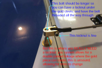
DON"T FORGET!! If you put a ball link in place you MUST use a lock nut to lock the gold clevis from turning on the stud.

Also I'll add that all these things you call "issues" are called "modeling" and the freedom of choice to modify. All of this stuff works just fine without any changes updates or mods. Jase and Gabby fly MKS and Gabby flies PAU hardware un-modified so it all works just fine.
 

Rusty 73

100cc
I believe that i have just as much freedom to post my "issues" and opinions as you do correct ?

I guess you and i come from different school of education , mine is Aircraft Maintenace engineering Technolgy , so maybe that's why I have different standards than you my friend :shake:. I try to "Do it right the first time ".

Well now you opened up the box about the hardware issues . Could you tell me why are the threaded bolts i received on my first Extra are only two and half inches an won't even support the PAU hardware through the ailerons. I had to swap out the hardware from a damaged PAU Extra and they were three inches, just long enough to get the hardware on the inside aileron. Pic below.
My Extra which was one from the first sea container DIDN'T have all the correct hardware and the back up hardware for a destroyed PAU Extra still didn't have the correct hardware . As you can see from my earlier post on ths Build .

So your saying that the gold H support thats threaded on the rod will move with the clevis ball links , Thanks for the heads up will have to redue the outboard aileron bolt with a three inched i have around , no mention of putting a nut on threads is mentioned in the manual .

IMG_2731.jpg


As you can see the two and half inch countersunk bolt i used for the out side doesn't have enough thread for a nut on the end.
The Distance from the hinge line to the clevis bolt is 1.49" and if I turn it in there is no room for a nut and i will screw up my mechanical matching to the 1.5" down to maybe 1.1" from centre line . Need the longer 3" bolts these as well .:cautious:
IMG_2732.JPG


IMG_2730.jpg
 
Last edited:

Terryscustom

640cc Uber Pimp
Wow. I can't speak for the hardware in your box, or any PAU box as I have nothing to do with it. I don't use the stock studs when doing the mod you are because they need to be slightly longer than those included to use the method you are using correctly. NOTE: YOU ARE NOT DOING IT LIKE WHATS IN THE MANUAL, HENCE THE LACK OF THE MANUAL NOTING A LOCKING NUT!!!! With your modified install CA or Threadlock on the gold clevis only works for a short while and then it will rotate and cause you trim issues. You only duplicated a portion of what I did to make it work so you may want to re-watch the videos if you wish to do it that way or check out the thread for the plane I was working on.

I was simply stating that some of the things you are pointing out like the original clevis that has a bushing inside it "would have failed", actually no because the bushing is the wear item. I won't debate the other stuff that I noticed as you already made clear your opinion and my degree in engineering probably does not trump the issues that are non-issues.

"I guess you and i come from different school of education , mine is Aircraft Maintenace engineering Technolgy , so maybe that's why I have different standards than you my friend" Well I'm glad I pointed out that you did not follow the videos to perform this mod correctly. I'll let you get back to your level of "standards". Good luck.
 

Rusty 73

100cc
I'm just i the propcess of setting up the servos and i will rematch your video which i have found to every helpful will doing this assembly .
I did change out the outboard studs for a longer 2.75" ones from the extra's hardware kit. I will be using a nut to prevent the gold clevis from turun from side to side and effecting the trim settings . Yes the manual doesn't talk about using a lock nut on the threads either.

I checked a few of the bushings in the clevis with a cailper and they had play it them about .002mm which i could feel .
This why I'm using the plastic ball joints so i don't have play:agree-disagree: .i just might use the original hardware later if i find an issue with wear on the ball joints, time will tell.
I have found that even small amounts of play in any of the linkage components can be lead to excessive wear on the linkage and also the gear train of the servo .
So i would rather have a super tight linkage set up with just about zero play ,
All of this comes from my racing background in the NMPRA, go fast and turn left around the pylons.:too-cool:

This are new MKS servo i just want them to last for a couple of years.:)
Will get back to the class room with your video , thanks :shake:

Russell
 

Islandflyer

GSN Sponsor Tier 1
Please note:
1- This plane is being fitted with several heavier items that will likely result in a heavy feel: OK for IMAC, but is will not 3D like Gaby's plane in the video above.
2- The is not V2 (therefore no V1) of this plane. Gaby and I have identical planes, that came with identical hardware. As the elevators (and counterbalances) are well oversized, the progressive wear on the gold hardware showed possible flutter, and we experimented with different hardware. The best replacement option we found if the 8-32 sets from Hangar 9. It is easy to re-tap the cone shaped nut.
3- For the elevators, is is equally important to have zero play in the servos in order to prevent any flutter at high speeds.
4- I have attached a picture to illustrate some of teh problems shown above that Terry tried to help with
 

Attachments

  • GSN Extra Issues a.png
    GSN Extra Issues a.png
    836.1 KB · Views: 396

Terryscustom

640cc Uber Pimp
Thanks Herve for posting reguarding this possible issue .:grouphug:

Yes the manual doesn't talk about using a lock nut on the threads either.

Just to clarify, there is no "issue" with the stock setup and you DO NOT want to use a lock nut. Once you introduce the ball link in there like you have, THAT is where the lock nut becomes important. Just want to make sure you understand what the point of the lock nut is.
 

Islandflyer

GSN Sponsor Tier 1
Correct: there needs to be one, and only one pivot point:
- The clevis on the stock hardware (or the H9 hardware that works the same way)
or
- The ball link
Not both
 
Top