cam4569
70cc twin V2
I got an opportunity to stop by and see @SupaTim at Northwest RC yesterday. What a great experience. I will admit I did a little drooling at first. His shop is clean and organized, he knew where everything was and had me set up in a matter of minutes. I picked up a 3DHS Slick 580 60" in the bright blue scheme. Here is a link to the airplane:
http://northwestrc.com/3D-Hobby-Shop--60-Slick-580--Blue_p_208.html
There are only a couple left and selling quickly from what Tim told me.
For my build I went with the following:
Torque 4016T/500KV
Castle Creations 90A ESC This thing is impressive, BEC output 8v and 20A. I was going to go with the standard Airboss but after talking with Tim I think this is the better option.
I picked up the Savox 1250MG servos 111 Oz of torque and .09 Sec speed ... WOW
Also picked up a couple Falcon Propellers to try, a 16x7 and a 16x8 Wood. I will be interested to see the amp draw with each runnign the Castle ESC.
My ESC will be programmed as follows: Soft start OFF, BEC 8V and Timing HIGH

The Goodies :banana::banana:

I will say they did not waste any money on the box, which is okay by me.

Everything was nicely secured in the box

The wings, SFG, wing tubes, and ailerons were inside the wing bags

Nicely painted Cowl and Pants

and the Bag O Parts


I will say I am very impressed with the quality of the finish on this plane. I looked and could not find a blemish or wrinkle anywhere. The control surfaces are attached but not glued into place. I was also surprised to learn that both styles of SFG are included in the box. the photo above I have both SFG as they would be mounted on the wing leading edge left. I have heard the "hatchet" style (one on the left) is "amazing" I am excited to try them out and see for myself.

You will notice that the firewall is not drilled, so any motor of the correct size can be used. The bag O parts has 4 bind nuts with Plywood spacers already attached so you can glue them into place where you need them. I also like how reinforced the motor box is. To go along with all the bracing you see on top the front of the firewall is fiberglass laminated.

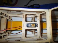
Huge improvement over my Extreme Flight Extra is the battery tray. This one is keyed into several of the former and looks much stronger.

This was hard to get a photo of but the landing gear bracing is a C channel of carbon fiber then there are two carbon fiber rods that go through it and through several of the former, It would take a lot to break theses loose.

There is carbon fiber everywhere in this Plane. I was also impressed to see that the pull pull cables were already run and tapped to the servo tray for ease of installation.
Now that I have all the parts out, Lets get to the fun part.

Locate the servo mounting locations on the bottom of the wing (Make sure it is the bottom)

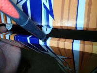
Use a very sharp hobby knife or a soldering iron, I like to use the hobby knife personally.

I like to cut well inside of the opening and leave about 1/8 to 1/4 inch "extra" that I will use my iron to wrap around the opening and seal the edges.

The edges have been cleaned up and I cut the opening for the horn in the aileron.

Using thin CA install the CA hinges. I could not get a photo of this due to lack of hands but what I do is slide everything together, hold the control surface at full deflection and add a couple drops of CA to the hinge, then repeat on the opposite side. A word of caution on this if you use to much CA and it drips over it may glue your control surface to your wing so Just a dab will do ya.

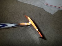
A photo of the gap that I have. I am not worried about this because I tape my joints with Blenderm. This gap gives me full deflection with no interference.

Again I ran out of hands to photograph this step. When tapping the joints be sure to move the control surface to full deflection and apply the tape from the inside trailing edge of the wing down into the gap, then tape the control surface. You want to make sure that the leading edge of the tape wont get caught in the wind and start to peal off. I personally tape top and bottom of the joint, if for no other reason it keeps the dust and dirt from sticking to the tape.

I checked to make sure i got full deflection with no resistance after tapping the joint.

I had to do a little fit and finish to get the control horns to sit in the slot, which I don't mind I would rather them be to tight than loose when I install them.

I prefer to dry fit the parts prior to glue/epoxy it is usually less messy that way.

I chose to use 30 MIN 2 part epoxy for the horns. After sanding the contacting area of the horn I used a toothpick and added epoxy to the gap in the aileron, then added more to the control horn.

Once I slid the horn into place it was easy to wipe up the excess from the joint.
I set the wings aside to dry overnight

Moving on to the landing gear. They included a small open end wrench that comes in handy.

There are no bind nuts and bolts or screws for the wheel pants, though if you want to drill some you could. instead the wheel gets placed on the axle first then the pants get sandwiched between the axle and the carbon landing gear.


It is a little tricky to get these put together with only two hands, a small vice to hold the carbon gear in place would have made the job a bit easier. Using the provided open end wrench and a socket tighten the axle bolt to the landing gear.

I had to remove a very small amount of material from the wheel pant to clear the tire. (mostly because I am a little OCD about friction)

On the bottom of the fuselage there are 2 installed bolts, using these bolts and the provided washers attached the completed landing gear assembly. I used lock tight on these bolts.

The landing gear has a straight edge and a tapered edge. The straight edge is the leading edge (toward the front)

There is a provided plate to clean up the install. I chose to use a couple spots of Welders adhesive here, you could also use sillicone or epoxy if you prefer.


A little overkill but I lightly clamped the parts together.
That is about it for one day, I hope to get some more done tomorrow. Still waiting on the mail man to bring the programming cable for the ESC.
http://northwestrc.com/3D-Hobby-Shop--60-Slick-580--Blue_p_208.html
There are only a couple left and selling quickly from what Tim told me.
For my build I went with the following:
Torque 4016T/500KV
Castle Creations 90A ESC This thing is impressive, BEC output 8v and 20A. I was going to go with the standard Airboss but after talking with Tim I think this is the better option.
I picked up the Savox 1250MG servos 111 Oz of torque and .09 Sec speed ... WOW
Also picked up a couple Falcon Propellers to try, a 16x7 and a 16x8 Wood. I will be interested to see the amp draw with each runnign the Castle ESC.
My ESC will be programmed as follows: Soft start OFF, BEC 8V and Timing HIGH
The Goodies :banana::banana:
I will say they did not waste any money on the box, which is okay by me.
Everything was nicely secured in the box
The wings, SFG, wing tubes, and ailerons were inside the wing bags
Nicely painted Cowl and Pants
and the Bag O Parts
I will say I am very impressed with the quality of the finish on this plane. I looked and could not find a blemish or wrinkle anywhere. The control surfaces are attached but not glued into place. I was also surprised to learn that both styles of SFG are included in the box. the photo above I have both SFG as they would be mounted on the wing leading edge left. I have heard the "hatchet" style (one on the left) is "amazing" I am excited to try them out and see for myself.
You will notice that the firewall is not drilled, so any motor of the correct size can be used. The bag O parts has 4 bind nuts with Plywood spacers already attached so you can glue them into place where you need them. I also like how reinforced the motor box is. To go along with all the bracing you see on top the front of the firewall is fiberglass laminated.
Huge improvement over my Extreme Flight Extra is the battery tray. This one is keyed into several of the former and looks much stronger.
This was hard to get a photo of but the landing gear bracing is a C channel of carbon fiber then there are two carbon fiber rods that go through it and through several of the former, It would take a lot to break theses loose.
There is carbon fiber everywhere in this Plane. I was also impressed to see that the pull pull cables were already run and tapped to the servo tray for ease of installation.
Now that I have all the parts out, Lets get to the fun part.
Locate the servo mounting locations on the bottom of the wing (Make sure it is the bottom)
Use a very sharp hobby knife or a soldering iron, I like to use the hobby knife personally.
I like to cut well inside of the opening and leave about 1/8 to 1/4 inch "extra" that I will use my iron to wrap around the opening and seal the edges.
The edges have been cleaned up and I cut the opening for the horn in the aileron.
Using thin CA install the CA hinges. I could not get a photo of this due to lack of hands but what I do is slide everything together, hold the control surface at full deflection and add a couple drops of CA to the hinge, then repeat on the opposite side. A word of caution on this if you use to much CA and it drips over it may glue your control surface to your wing so Just a dab will do ya.
A photo of the gap that I have. I am not worried about this because I tape my joints with Blenderm. This gap gives me full deflection with no interference.
Again I ran out of hands to photograph this step. When tapping the joints be sure to move the control surface to full deflection and apply the tape from the inside trailing edge of the wing down into the gap, then tape the control surface. You want to make sure that the leading edge of the tape wont get caught in the wind and start to peal off. I personally tape top and bottom of the joint, if for no other reason it keeps the dust and dirt from sticking to the tape.
I checked to make sure i got full deflection with no resistance after tapping the joint.
I had to do a little fit and finish to get the control horns to sit in the slot, which I don't mind I would rather them be to tight than loose when I install them.
I prefer to dry fit the parts prior to glue/epoxy it is usually less messy that way.
I chose to use 30 MIN 2 part epoxy for the horns. After sanding the contacting area of the horn I used a toothpick and added epoxy to the gap in the aileron, then added more to the control horn.
Once I slid the horn into place it was easy to wipe up the excess from the joint.
I set the wings aside to dry overnight
Moving on to the landing gear. They included a small open end wrench that comes in handy.
There are no bind nuts and bolts or screws for the wheel pants, though if you want to drill some you could. instead the wheel gets placed on the axle first then the pants get sandwiched between the axle and the carbon landing gear.
It is a little tricky to get these put together with only two hands, a small vice to hold the carbon gear in place would have made the job a bit easier. Using the provided open end wrench and a socket tighten the axle bolt to the landing gear.
I had to remove a very small amount of material from the wheel pant to clear the tire. (mostly because I am a little OCD about friction)
On the bottom of the fuselage there are 2 installed bolts, using these bolts and the provided washers attached the completed landing gear assembly. I used lock tight on these bolts.
The landing gear has a straight edge and a tapered edge. The straight edge is the leading edge (toward the front)
There is a provided plate to clean up the install. I chose to use a couple spots of Welders adhesive here, you could also use sillicone or epoxy if you prefer.
A little overkill but I lightly clamped the parts together.
That is about it for one day, I hope to get some more done tomorrow. Still waiting on the mail man to bring the programming cable for the ESC.
Last edited by a moderator: