• If you are new to GiantScaleNews.com, please register, introduce yourself, and make yourself at home.

    We're 1st in Giant Scale RC because we've got the best membership on the internet! Take a look around and don't forget to register to get all of the benefits of GSN membership!

    Welcome!

105" AJ Laser Build Thread

jhelber08

70cc twin V2
So while at Joe Nall I made a split second decision that I just had to have a 105" AJ Laser and it just so happened that they had a trailer full (well at least one of them any ways) and I brought it home with me in the Patriot Scheme. I'm going to make my first attempt at doing a build thread so that hopefully I can help someone who is setting up a large scale 3d/XA machine for the first time and to get input from others who may have some better ideas on how to do things. I've already started on the build so will summarize what I have done so far below and get some pics up as soon as I figure out how to resize a batch of photos in windows 10 (unfortunately my trusty old mac is at the dr's office at the moment so I'm using a new laptop).

For starters I'll list out the equipment I plan to use.
Engine: DA-120 with Tech Aero IBEC
Prop: Falcon 29x9 with some bling from @Terryscustom, will also be playing with a 27x11 a little but 29x9 has been my prop of choice on the DA120.
Servos: Wings/Stabs will be using MKS HBL 599's. I haven't decided on the rudder but I will either be using a single MKS 380 or two savox 2270's I have laying around so I can move the 380 to one of my other planes that needs some more umph on the rudder.
Batteries: 2x Pulse 3300 RX batteries
RX - Spektrum 12ch Powersafe RX with Failsafe switch
Other accessories:
- SWB arms (2" on stabs, 4" offset for rudder, 1.5" on ailerons). I have some of the new extreme flight 2" arms on order and may try those out as well if they show up in time.
- Taildragger 34 oz fuel tank, Taildragger wiring and MPX dual wing harnesses.

Let the fun begin!
 

jhelber08

70cc twin V2
I'm starting out a little late in the thread so here is a quick run down of what I've got so far. I apologize that I do not have any unpacking pics as some of the unpacking occurred at Joe Nall in order to be able to squeeze this thing in the trailer. However from the looks of the box and construction of the fuse I would say that it looks like the planes are coming from the same factory as 3DHS. The included hardware and little odds and ends are identical to what you find with 3DHS along with many extra nuts/bolts. The packaging is top notch as well and the plane is very well protected and arrived with hardly any wrinkles. The plane also comes with what appears to be a 6" Omega Carbon Fiber Spinner (no bolt though so you will have to supply your own, I believe @vegasking or @SupaTim carry the right length bolts or you can also source from local hardware stores, should be 5mm x ~115mm long). The plane also comes with some nice cloth wing and stab backs embroidered with the AJ Aircraft logo. One thing not to forget before you throw your box away is the hinge pin for the rudder, you will find it taped to the inside of the box with the fuse. I'll get some pics of this stuff at a later time.

Engine Mounting:
Prior to mounting any gear, I stood the fuse up against the wall and centered the engine up to the cowl. I will be using the 1" blazing star mount that I already had on hand. The mount actually measures out to be 1.125" where as the supplied 1" stand offs will work as well. I ended up having to send my 120 in for a check up but was able to get the firewall drilled and checked for alignment. The pic below shows a DA100 drill guide supplied with the kit. Due to the extra length of the blazing star mount and the right thrust built into the firewall, my mounting holes are shifted by about 1/32-1/16 of an inch as seen in the photo below. If using the supplied stand offs or a true 1" mount, you should be pretty spot on to use the included guide.

DSC00975 (640x480).jpg


Landing Gear:
Next thing I did was prepare and install the landing gear and gear cuffs. I can honestly say this is the first arf I have put the landing gear and cuffs on without cussing or having to modify axles/wheel pants to get everything to fit the way I want it. Again no pics of this step but it is pretty straight forward. The wheels supplied are very nice with metal hubs. The hubs screw together with 4-40 screws. One thing I do on these types of wheels is to remove all the screws and apply blue loctite and then re-assemble. The gear are air foiled so remember to mount with the thickest side pointing towards the front of the airplane. Bolt the gear to the fuse using the supplied bolts, lock nuts, and lock washers and remember to use a drop of loctite. Next install the gear plate with a bead of goop. After that, install the cuffs. They already come assembled with neoprene tubing around the openings and are made to be screwed to the gear legs however I lined them up, marked the gear, scuffed the gear with 80 grit paper and used goop to secure to landing gear. This will give a little more play in the event of a hard landing/gear flex and protect the side of the fuse as well as the cuffs from damage. Next thing was to install the supplied axles and wheel collars. This is a pretty standard installation by fitting the wheel pants for correct spacing and then grinding a flat spot on the axles for the collar set screws. Top it off with a little loctite and you should have a setup that will last for several years before requiring any maintenance. I also attached a J&J tailwheel I had laying around just so the tail can be off the ground, I'll get to the final install of this once I install the rudder.
DSC00986 (640x480).jpg


Control Horns:
Usually when installing control horns, I take the time to seal the hinges. However, the Laser comes pre-hinged and sealed so this is a big plus. I do like to glue my own hinges so I know its right but these look great from the factory with very little gap and I'm able to get the throw that I need without any binding. The control horns supplied are composite. Again, no pics of this step but it is pretty straightforward and typical of any arf out there. Utilize some sand paper to scuff the areas of the control horn that insert into the control surface. Prepare the surface by removing the covering and test fit the control horns to the surface. I found that I had to clean some of the mounting holes a little bit with a small file in order to get the horns to seat all the way. I also mask around the area on the control surface to aid in clean up of any epoxy/glue that seeps out in the process. My glue of choice is Hysol for this step. Typically I use Hysol 9462 however I was out but had some E20HP that is a little quicker setup time and will still work great for this application. Using the hysol glue tip, shoot a little glue in the control surface and slide in your control horns. Take care to ensure the control horn centers above your hinge line and adjust during the dry fit if necessary to achieve this. I found that even with the tight fit of the control horns, they all came out dead center over the hingeline without any modifications. Once you have your control horn in the surface, screw a ball link in to keep the control horn straight and true. You will find two types of ball links included in the hardware, one will have a spacer which is for your servo arm and the other will not have a spacer and this is for your control horn.
DSC00981 (640x480).jpg DSC00988 (640x480).jpg

A few other things to note:
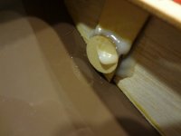
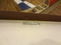
While I had the glue gun out, I hit some problem spots on the canopy. The mounting tabs and carbon dowel rods on the front will eventually come loose on any plane, especially with a DA120 honking up front. So before that happens I usually re-enforce with some epoxy while I'm thinking about it. The first Slick I ever built, the canopy came apart on the third flight and I've seen numerous folks take off and do a pop top only to have their canopies fly off and its usually because the dowel rods up front have shaken loose. So this is a must and you should periodically check these areas when you're assembling at the field. I keep some 5 minute epoxy in the trailer for things such as this.

DSC00983 (640x480).jpg DSC00984 (640x480).jpg
 

Attachments

  • DSC00983 (640x480).jpg
    DSC00983 (640x480).jpg
    168.5 KB · Views: 496
  • DSC00984 (640x480).jpg
    DSC00984 (640x480).jpg
    154.1 KB · Views: 513

jhelber08

70cc twin V2
Next up on the list is installation of the aileron servos.

First, the laser comes with some string routed through the wing to assist with fishing out your servo wires. I first move these strings out of the way and insert a servo in the opening and drill and mount the servo using #2 servo screws from RTL. I like these screws because you can use an allen head as opposed to a phillips screw driver that ends up striping the head. Once mounted I pull the servo out and go over the mounting holes and mounting location with a healthy dose of thin CA. This step is very important and one that I've learned not to skip as I have had servos pulled out of wings before due to insufficient glue and my somewhat aggressive attempt at flying. Once the CA cures I prep the servo and extensions for final install. I like to use servo safety clips along with a wrap or two of electrical tape to keep the plugs from unseating. There are many ways to do this such as heat shrink, thread, fishing line, dental floss, etc. However to me this is the easiest and easiest to replace at the field if need be. I've also had safety clips come undone when installed in permanent locations. They will work for short periods of time but have come loose on me inside wings and stabs where they are not removed for several hundred flights so I now add the tape for a more permanent install. I've also had heat shrink work itself to be just loose enough over time as well to cause intermittent servo failure and that is when I switched to using clips. One other thing to note is the fiber servo washers installed on top of the servos. I've started using these recently and have found that they provide a much more solid mount to the airframe. They can also be used as shims underneath the servo for deep servos such as the MKS 777s which sometimes will interfere with the top of the wing on planes with thin wing foils.

DSC00977 (640x480).jpg DSC00978 (640x480).jpg DSC00979 (640x480).jpg DSC00980 (640x480).jpg
 

jhelber08

70cc twin V2
Now onto setup. There are several ways to skin this cat but this is what I've started doing lately and have found that it makes it quite easy to set up and match dual servos on an aileron.

First order of business is to find out how long you really need your servo arm/control horn for the best mechanical advantage. Start by measuring the distance between the ball link and hinge line. On the out board servo I found the distance from the top mounting location on the horn to be roughly 1-3/4" and on the in board servo I found the middle hole provided a distance of 1-3/4" as well. Several key points to remember here are that you want the distance from the ball link to the hinge line to be as long as possible to provide the best advantage. Also, for multiple servos, you want this distance to be equal to provide a more consistent and equal travel throughout the range of motion. So now I know that I do not want to use anything longer than 1-3/4" for my servo arm or else I will not have a greater than 1:1 advantage. I typically shoot for roughly 40 degrees of throw when setting up my ailerons. I find that this gives me a fast consistent roll rate without slowing the plane down. Next you want to properly center your servo. Contrary to popular belief, setting your arm to be perpendicular to the servo or parallel to the hinge line does not achieve a proper center when shooting for large amounts of throw however it is typically a good starting point for surface mount servos. To find the center I start with the arm parallel to the hinge line and then install my linkage and adjust the length until the surface is centered. I then set my travel to roughly 130 (Spektrum, not sure about futaba or other brands but spektrum has a full range of +/- 150). From there I check and see how much travel I get in both directions. I started with the linkage installed at 1.5" on the servo arm and by eyeballing it I was getting 50+ degrees of throw so I moved in to the 1.25" hole on the arm. From there, with 130 for travel I was getting roughly 41-42 degrees down and 36 degrees up. So here is where true center comes into play, the goal is to get equal travel up and down with equal atvs as this will make balancing the servos much easier later on. Sure you can adjust your endpoints a little to get equal travel up and down but when you set up dual rates you will most likely find that you will not have equal travel then which will cause less axial rolls at low rates. So what you want to do is now adjust your subtrim towards the direction that you are getting the most throw and then adjust your linkage to recenter the surface. After a little guess and check I found that I was getting 39 degrees up and 39 degrees down which is close enough. Another thing to note is how much sub trim you end up with as this will eventually effect your end travel if you have too much. So while you're doing this, watch your servo monitor to ensure you are not maxing out at full throw. It maybe necessary to move your arm by one tooth and reset your subtrim so that it is as low as possible. With the subtrim on one of my servos, due to the fact that true center was right in between one tooth, I came close to maxing out the travel and was only able to get 39 degrees and still leave a touch of headroom. After you do this with one servo, repeat the process for the other and ensure you are getting the same amount of throw up and down with equal atv up and down. I can honestly say that the geometry on the laser has been pretty spot on and this has been one of the easiest to set up. Usually when I set up my wings this way with composite control horns (vs. the screw type) I end up with one servo that has a +/- atv of 130 and the other around +/- 120 This is not a bad thing, the important thing is that they travel equally up and down with equal ATV. These both were pretty spot on with an ATV of 130. I used a digital angle finder to measure and as well measured with a ruler and found my travel to be 130mm up and down.
DSC00973 (640x480).jpg DSC00974 (640x480).jpg


Once center is found on both servos, its time to check for any binding between the servos. One thing I started doing once I have my servos centered is to power the plane down and then run a straight edge across both servos to check their alignment. This assures that both are parallel to the hinge line at the same time. Mix that with them being centered and travelling equally up and down and you pretty much have the servo matching licked.
DSC00971 (640x480).jpg

From there, the first place I check for binding is when the surface is centered. I think I may have added one click of subtrim on this setup for the servos to be completely quiet. I also check by seeing whether or not the bolt in the ball link can be freely inserted and tightened. Next I check for binding at full throw by listening to the servo and again checking how freely the screws move. Usually, due to flex in the control surface and depending on where you measure your throws in the steps above, I will have to adjust the end points on one servo slightly to get rid of any binding at full swing. On this one I chose to adjust the inboard servo and ended up with final ATV's around +132/-127 which is close enough as a few points off will not hurt. From there you should now have a pretty bind free setup and this can easily be checked with a current meter such as the fromeco quad meter. I haven't done that yet but really feel that it doesn't need it based on what I'm hearing and feeling. The final step I do with the DX18 is check for throughout the travel using the balance feature. I will set up some dual rates so that my travel lands on the balance points at full stick and adjust the travel at these points until any slight buzzing disappears. I ended up making very little adjustments (like + or - 5 points in the balance feature). Prior to going through this process and relying strictly on the balance feature, the little graphic on the balance screen looked like a saw tooth because they were so out of wack...doing it this way makes them come out pretty straight with very little adjustment needed.

I hope this makes sense and not just in my head because I'm tired and running on fumes at this point. It seems like a task at first but after you do it a few times, you will find that it is pretty painless and provides a pretty robust setup.
 

Snoopy1

640cc Uber Pimp
Looking good I am presently looking AJ 50cc plane but it is not out yet. Did you see it at JoeNull. If you did, did you look at it and what did you think.
 
I have about 10 flights on mine now. DA 120 and MKS 777 for elevator and rudder. Because of the thin wings I ended up buying some Savox 2270's. I put this together during Joe Nall week so it was hard to locate some MKS servos. But the savox will be fine. I did start as a pull pull rudder setup but since it was really nose heavy I was able to place the rudder servo in the tail as push pull. Now my batteries are next to my fuel tank. So far it fly's really nice. Very little mixing. I really like the Falcon 27x11x2 because of the speed and thrust. The 29x9x2 is much slower but has some good low end power.
 
I think I may have to open up the air inlet holes in the cowl. This plane does not seem to allow this engine to cool down at all. Today I hit over 400F during some water falls. It cooled down once I got moving again but cooling is an issue. I first started with the classic ducting to the front of the fins. Not really good. I wrapped the fins in ducting and it made a difference. But it still does not seem to be getting much air through it. So I will be opening up the 2 air inlets.
 

jhelber08

70cc twin V2
Looking good I am presently looking AJ 50cc plane but it is not out yet. Did you see it at JoeNull. If you did, did you look at it and what did you think.

I did see it at Joe Nall. I didn't really get up close to it though to check it out. Andrew did bring it out to the 3d line one night and flew the snot out of it. It looked like it flew really well and I imagine if its anything like the laser or the AJ slick it will be a winner as well.
 

jhelber08

70cc twin V2
I have about 10 flights on mine now. DA 120 and MKS 777 for elevator and rudder. Because of the thin wings I ended up buying some Savox 2270's. I put this together during Joe Nall week so it was hard to locate some MKS servos. But the savox will be fine. I did start as a pull pull rudder setup but since it was really nose heavy I was able to place the rudder servo in the tail as push pull. Now my batteries are next to my fuel tank. So far it fly's really nice. Very little mixing. I really like the Falcon 27x11x2 because of the speed and thrust. The 29x9x2 is much slower but has some good low end power.

Yes these wings are very thin. On my demonstrator I am using 777's and ended up having to shim them up a hair on the outboard servos because they were starting to poke into the top of the wing.

From what Andrew showed me at Nall, he has his balanced in front of the wing tube with the canopy off. I will start with a pull pull and see where that gets me. I'm hoping my batteries will end up just in front of the rudder servos to put me where his mark was. Being that I'm using a blazing star mount which pushes the engine fwd an 1/8th of an inch, I may end up running push pull when its all said and done. I wish my engine was here so I could throw it together and balance it.

I need to update where I'm at now. I've pretty much got everything done as far as I can go until my engine gets back from DA. I will probably start adding pics and update tomorrow.
 
Top