GSNadmin
Staff member
So now that we have come to a natural breakaway point with the fuselage, it’s a good time to begin the wing construction. Eventually we will return to the fuselage for the firewall and engine installation, but for now, lets work with some ribs.

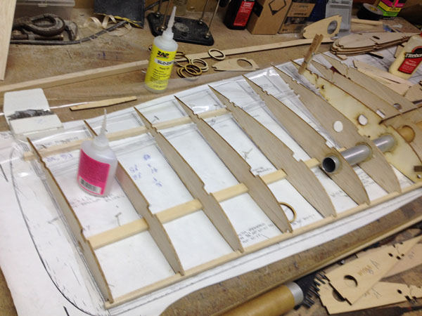
After cleaning up all the debris from the fuselage build, lay out the plans for the wing and cover with clear plans protector material. Here all the ribs and spare reinforcement parts have been sorted out and it is a good time to plan the build in your head. What needs to be done first and when things need to be glued. “Think Building” is a very important part of any project.

So the very first thing to do is to cut the bottom spar, (made of 1/4×1/2-in. spruce for the Skyraider), and then glue the center reinforcement web in place, (I used thick Zap CA). Once they have been glued together, I pinned the spar in place over the plans. Since they are made of spruce, the T-pins should be inserted into the sides of the spar in between rib locations.
 You can see here that the washout shim has also been pinned in place to lift the tail ends of the ribs off of the plans. I like to start with the tip rib and work my way toward the center of the wing.

Use a square or triangle to keep the ribs square to the building board. I just use a small dab of glue to tack the rib to the bottom spar. I then go back over all the glue joints with thin Zap CA after everything is tacked together. This allows any fine tuning or replacing of parts should you make a mistake in the assembly.

I next glued the lite-ply doublers to the center rib to form the inner channel for the center wing alignment dowel. I use Titebond yellow wood glue for this and weigh the parts down until the glue has dried.
Once the tip and the center ribs are pinned in place I then use the main spar as the guide for the rib locations placing each in place and tack gluing it so it does not move. There is a 1/4-inch square balsa strip that tie the fronts of the ribs together. This is not glued in place until all the ribs are glued to the spar. This way, you can adjust the leading edge strip if needed to make sure it is straight. I use a metal yard stick to check it for straightness as the build progresses.

At this point, you have to decide whether you want a 1-piece wing or you want to build it with plug-in outer wing panels. Here is the wing joiner tube and cardboard sleeve fitted into place, None of the ribs have beek tack glued into place yet. The double rib W-10 form the separation point of the inner and outer wing panels.
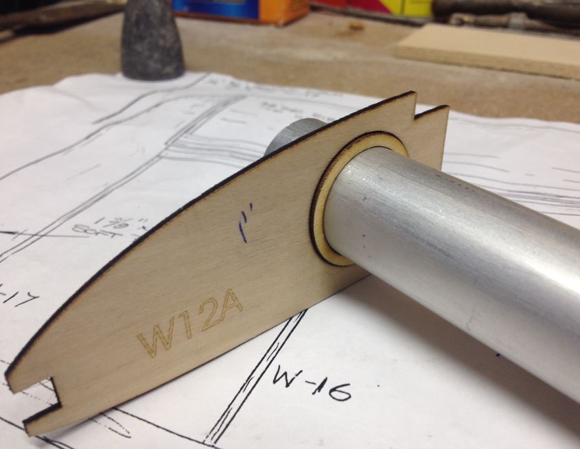
My laser cut parts were cut with the tube holes cut for a 1.5 inch tube. I am using a 1 inch diameter tube so I cut these alignment rings out to keep the tube centered. Everything is a loose fit to make sure everything aligns properly. Remember the laser cut parts are only as good as the plan drawings and sometimes there may be a misalignment here or there, so do not be in a rush to start gluing things together.

Here you see both the outer half of the joiner tube, it has been centered in the ribs and the larger glue reinforcement rings have been slide into place. Looking at the upper right corner of the photo you can see that the tube sleeve in the wing center section is not centered exactly in the hole in the rib. If I had glued the rings in place, the tube would not slide into position. Take your time with this. Also note there are plywood doublers in either side of the two separation line ribs. These strengthen the ribs and the joiner tube assembly.

So here we see the inner tube sleeve in position with all the rings in place. Everything is now in proper alignment and you can start gluing the assemble to the ribs. Doing this also locks these ribs into position so be sure all the ribs are in the proper positions and that the tails of the ribs are pinned into place along the length of the washout shim. The shim strip runs from the tip to the W-3 rib. Ribs W2 and W1 have alignment tabs attached to their bottoms which will be cut away before sheeting.
After the tube and sleeve have been glued in place with thin and medium Zap, you can go ahead and glue the top main spar in place with thick Zap and then after checking everything’s alignment again, go ahead and glue all the glue joints of the wing assembly, except for the plywood ribs that will support the retractable landing gear.
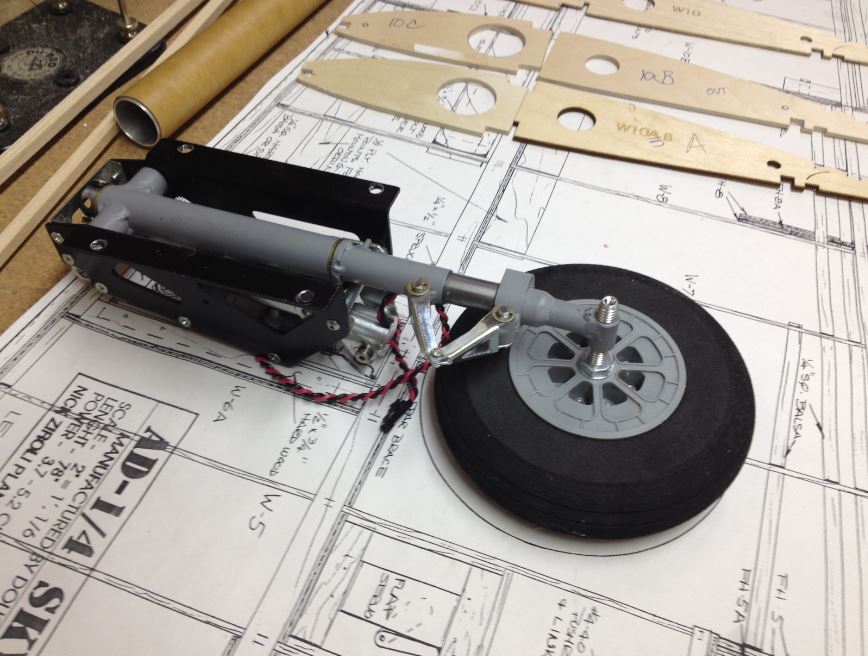
Here’s the Robart 148E electric 90-degree gear placed on the plans for a quick look to see what needs to be done while installing them.

So this is the section of the wing that the retracts will be located. One of the caveats of resizing any set of RC plans is that the hardware available may not match the reduced details on the plans. For the 100 inch Skyraider, the plans show the Robart #150 gear. You can see the notches cut in the vertical plywood web which would position the mount rails for the larger airplane.

Here are the plywood ribs that will support the gear, along with a sheeting support piece and my mount rails.
Robart Retracts
The landing gear I am using for the 85 inch version of the Skyraider are the Robart 148E. Very similar to the #150s they are smaller with shorter struts but wider than the plans show.

Electrically driven, these gear are well engineered and the design is well tested, as they are used in many of the giant scale Top Flite Warbird ARFs like the P-40 and F4U Corsair. To make them fit properly, the gear will be used as a spacing guide so you do need to have them on hand before you can finish your wing.
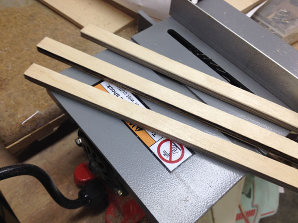
For the mounting rails that will be epoxied to the plywood support ribs, I used my 4-inch table saw to cut 1/4-inch plywood into 1/2-inch-wide strips. These will then be laminated together with 15-minute Zap Z-Poxyy and clamped together until the adhesive has cured. The end result is produce the needed 1/2×3/4-inch rails.

The long sides will be epoxied against the ribs and the gear will be supported by the 1/2 inch wide edges. The next step will be to lift the wing panel from the workbench and block up the wingtip to the proper dihedral angle. This will then allow us to install the plywood ribs at a 90 degree angle to the workbench, giving us straight gear struts when the wing panels are joined.
Installing the gear support ribs will be shown in the next post in this Build-Along series, so stay tuned.
For previous post: CLICK HERE.
Model Airplane News - The #1 resource for RC plane and helicopter enthusiasts featuring news, videos, product releases and tech tips.
Continue reading...
After cleaning up all the debris from the fuselage build, lay out the plans for the wing and cover with clear plans protector material. Here all the ribs and spare reinforcement parts have been sorted out and it is a good time to plan the build in your head. What needs to be done first and when things need to be glued. “Think Building” is a very important part of any project.
So the very first thing to do is to cut the bottom spar, (made of 1/4×1/2-in. spruce for the Skyraider), and then glue the center reinforcement web in place, (I used thick Zap CA). Once they have been glued together, I pinned the spar in place over the plans. Since they are made of spruce, the T-pins should be inserted into the sides of the spar in between rib locations.
You can see here that the washout shim has also been pinned in place to lift the tail ends of the ribs off of the plans. I like to start with the tip rib and work my way toward the center of the wing.
Use a square or triangle to keep the ribs square to the building board. I just use a small dab of glue to tack the rib to the bottom spar. I then go back over all the glue joints with thin Zap CA after everything is tacked together. This allows any fine tuning or replacing of parts should you make a mistake in the assembly.
I next glued the lite-ply doublers to the center rib to form the inner channel for the center wing alignment dowel. I use Titebond yellow wood glue for this and weigh the parts down until the glue has dried.
Once the tip and the center ribs are pinned in place I then use the main spar as the guide for the rib locations placing each in place and tack gluing it so it does not move. There is a 1/4-inch square balsa strip that tie the fronts of the ribs together. This is not glued in place until all the ribs are glued to the spar. This way, you can adjust the leading edge strip if needed to make sure it is straight. I use a metal yard stick to check it for straightness as the build progresses.
At this point, you have to decide whether you want a 1-piece wing or you want to build it with plug-in outer wing panels. Here is the wing joiner tube and cardboard sleeve fitted into place, None of the ribs have beek tack glued into place yet. The double rib W-10 form the separation point of the inner and outer wing panels.
My laser cut parts were cut with the tube holes cut for a 1.5 inch tube. I am using a 1 inch diameter tube so I cut these alignment rings out to keep the tube centered. Everything is a loose fit to make sure everything aligns properly. Remember the laser cut parts are only as good as the plan drawings and sometimes there may be a misalignment here or there, so do not be in a rush to start gluing things together.
Here you see both the outer half of the joiner tube, it has been centered in the ribs and the larger glue reinforcement rings have been slide into place. Looking at the upper right corner of the photo you can see that the tube sleeve in the wing center section is not centered exactly in the hole in the rib. If I had glued the rings in place, the tube would not slide into position. Take your time with this. Also note there are plywood doublers in either side of the two separation line ribs. These strengthen the ribs and the joiner tube assembly.
So here we see the inner tube sleeve in position with all the rings in place. Everything is now in proper alignment and you can start gluing the assemble to the ribs. Doing this also locks these ribs into position so be sure all the ribs are in the proper positions and that the tails of the ribs are pinned into place along the length of the washout shim. The shim strip runs from the tip to the W-3 rib. Ribs W2 and W1 have alignment tabs attached to their bottoms which will be cut away before sheeting.
After the tube and sleeve have been glued in place with thin and medium Zap, you can go ahead and glue the top main spar in place with thick Zap and then after checking everything’s alignment again, go ahead and glue all the glue joints of the wing assembly, except for the plywood ribs that will support the retractable landing gear.
Here’s the Robart 148E electric 90-degree gear placed on the plans for a quick look to see what needs to be done while installing them.
So this is the section of the wing that the retracts will be located. One of the caveats of resizing any set of RC plans is that the hardware available may not match the reduced details on the plans. For the 100 inch Skyraider, the plans show the Robart #150 gear. You can see the notches cut in the vertical plywood web which would position the mount rails for the larger airplane.
Here are the plywood ribs that will support the gear, along with a sheeting support piece and my mount rails.
Robart Retracts
The landing gear I am using for the 85 inch version of the Skyraider are the Robart 148E. Very similar to the #150s they are smaller with shorter struts but wider than the plans show.
Electrically driven, these gear are well engineered and the design is well tested, as they are used in many of the giant scale Top Flite Warbird ARFs like the P-40 and F4U Corsair. To make them fit properly, the gear will be used as a spacing guide so you do need to have them on hand before you can finish your wing.
For the mounting rails that will be epoxied to the plywood support ribs, I used my 4-inch table saw to cut 1/4-inch plywood into 1/2-inch-wide strips. These will then be laminated together with 15-minute Zap Z-Poxyy and clamped together until the adhesive has cured. The end result is produce the needed 1/2×3/4-inch rails.
The long sides will be epoxied against the ribs and the gear will be supported by the 1/2 inch wide edges. The next step will be to lift the wing panel from the workbench and block up the wingtip to the proper dihedral angle. This will then allow us to install the plywood ribs at a 90 degree angle to the workbench, giving us straight gear struts when the wing panels are joined.
Installing the gear support ribs will be shown in the next post in this Build-Along series, so stay tuned.
For previous post: CLICK HERE.
Model Airplane News - The #1 resource for RC plane and helicopter enthusiasts featuring news, videos, product releases and tech tips.
Continue reading...