• If you are new to GiantScaleNews.com, please register, introduce yourself, and make yourself at home.

    We're 1st in Giant Scale RC because we've got the best membership on the internet! Take a look around and don't forget to register to get all of the benefits of GSN membership!

    Welcome!
  • Unless you are a paid advertiser NO more posting advertisement in the individual vendor forums. You may post in the Manufacturer's Announcements section only but only ONCE a month unless your a paid advertiser.

My 3DHS BIGFOOT build

My 3DHS BIGFOOT build STARTED AUG 3rd..

Hello all,, I am posting my build from another forum on my bigfoot that I have been working on for about a week now, this post moves quick because I am listing a lot of work all at once IF YOU HAVE ANY QUESTIONS FEEL FREE TO ASK I WILL DO MY BEST TO ANSWER
I was looking for a high wing plane that I can help my wife learn better on so she can fly at big bird fly ins, and of course one that I can put on high rates and have some fun with it,, I decided to go with the bigfoot because of its aerobatic capabilities and huge flaps for slow flying, I believe it is a much better flying plane than a decathalon and easily more than a cub when it comes to its limits. I am going to post up my build of my new 3dhs bigfoot, I plan on taking alot of pics, and describing what I Like and dont like about the plane, and including actual costs,,If you are interested keep reading I will try to cover everything completely. be patient because I work rotating shifts, and will work on it when I can, but I hope to have it done in around a month
I have built about 12 planes now, most arfs and two were complete rebuilds including structure repair, I dont proclaim to know everything, but I am very confident in my skills and abilities, I am an industrial maintenance tech by trade so you may see some Ideas that are a little different but they work,,so I will proceed.
Got the plane today, I pre-ordered it from 3dhs and got free shipping, it looks like it sold out on the presales,, dont think you can get one, I settled on the black one,
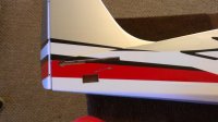
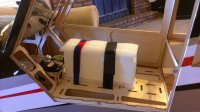
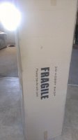
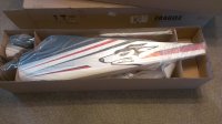
Arrived Double Boxed, and in good shape, opened the box to start the inspection, plane is packaged in very well, and secure, inspection revealed no damage to plane at all.
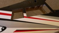
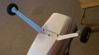
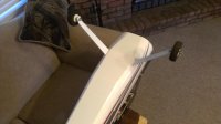
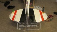
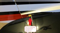
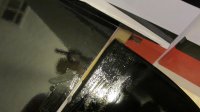
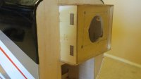
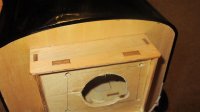
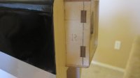
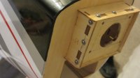
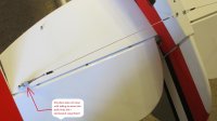
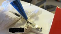
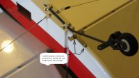
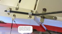
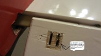
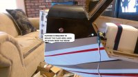
Hardware looks adequate, color scheme is terrific, plane comes with graphics, I dont believe I will be using any of the graphics, maybe a few of the small ones but none of the larger ones. Sturdy aluminum gear, carbon fiber wing tube, all seams on covering look good and the lines match up very well. The wings already have the hinges for the ailerons and flaps glued in, although it appears as though one of my flap hinges is broken, I will deal with this later, the hinges are like robarts, not dubro, and not junk CA hinges. However the door on the side is held on with CA hinges, since this is not a conrtrol surface and has no load, they will work great. The side door has the hinges, and magnets to keep it closed, the top hatch is also hinged, and has magnets, so getting to the wing bolts and plugging in the connections should be a breeze as there is plenty of room.
thats it for today, gotta get some sleep
current costs,, Plane $540 to my door
 

Attachments

  • IMAG0582.jpg
    IMAG0582.jpg
    52.5 KB · Views: 498
  • IMAG0584.jpg
    IMAG0584.jpg
    176.2 KB · Views: 385
Last edited by a moderator:
Got a little bit done before work,
Mounted the landing gear with supplied hardware, Using Blue Loctite, put wheels and collars on, with retaining pins, then put gear cover panel on, I used some very thin very sticky double sided tape that I have.
Then I got to removing covering , when built they cover the servo openings, horizontal stab hole, wing tube holes, windows, ETC..
You have the option to use a pull pul setup for electric power, or a rear mounted servo for gas,, I am using gas so I am using a rear mount,, I however did open the pull pull holes, why, because the plane arrived with the cables installed and the covering cut, I just opened it up and sealed it, no ones gonna notice.
There are several ways to remove the covering, some use exacto knives, razors, soldering irons, ETC.. The method I use is I take a map gas torch,,Like a propane torch for plumbing, I use a small straight PICK and heat it up with the torch, when its glowing I push it into the hole, go to the edges and just slide it along to remove the covering, I like doing it this way because it gives me clean lines, and the heat from the pick helps the edges of the covering seal back down on the edge of the opening. Always works great for me.
Thats as far as I got today, off to work
 

Attachments

  • IMAG0587-1.jpg
    IMAG0587-1.jpg
    70.6 KB · Views: 409
  • IMAG0590.jpg
    IMAG0590.jpg
    139 KB · Views: 374
  • IMAG0591.jpg
    IMAG0591.jpg
    118.7 KB · Views: 359
  • IMAG0592.jpg
    IMAG0592.jpg
    123.5 KB · Views: 404
  • IMAG0593.jpg
    IMAG0593.jpg
    130.3 KB · Views: 406
ENGINE HAS BEEN BOUGHT!!!

I really only wanted one particular engine for this plane, THE DLE35-RA

Another member on RCG was selling one and I was able to get it for a fair price, saved me some cash,, only 1 gallon thru it, Paid 270 shipped for the engine


Total costs so far,
plane 540
engine 270
$810
 
Last edited by a moderator:
August 4th

Ok, today gonna install the rear vertical and horizontal stabilizers...
DISLIKE: the plane did not come with a manual,not too much of a problem, because I downloaded it on thier site, but if you are not into computers,, it can be a problem.

FIRST THINGS FIRST,, pre fit both stabs, and the wing tube, line them up and get behind the plane on a level surface and make sure they look even both up and across, if not do a little sanding to get them there,,, MINE looked perfect and needed nothing from what I seen

HORIZONTAL STABILIZER,, fairly straightforward, I installed it in its slot, And got it all lined up, THEN I DIDNT FOLLOW THE INSTRUCTIONS AND DID IT MY WAY,, In the instructions it says not to remove any covering and then to get it into position, and then put thin ca thru the gaps because there is bare wood for it to wick into in the slot, I am not a fan of that idea, it may work fine, but it is not up to my standards of building. So what I did was slid it into place, lined it all up and then drilled 2 5/32 holes thru the fuselage into the stab and back into the bottom of the fuselage so I could install some 1/8 in dowels., I then made some marks on the edges, then pulled it out, removed some covering, put epoxy on the stab on both sides, in the holes I drilled and inside the fuse ( I taped the side that I slid into the fuse so no epoxy would get on it, I then slid it into the fuse, lined it up, Installed the dowels, removed the tape, and cleaned all excess epoxy. The dowels accomplish 2 things A: they help line the stab back up on final install B: it also ads plenty of strength when everything is dry.

Vertical stab, this was pretty simple, epoxy inside fuse where it goes, and epoxy on the stab, it sits in a slot that is nice and tight, ONCE again the instructions say you can use CA,, I chose not to, I use EPOXY One thing about the stab is on pre-install I noticed that it stuck out of the rear of the fuse a little bit, to me this is a problem and needs to be fixed, with that difference the rudder gap will not be able to be closed properly. Easy fix, used a razor, trimmed a little bit off of the leading edge of the stab, little bit of sanding and everything looked great, Epoxied it in and its done.
I epoxied the horizontal stab in place then immediately did the vertical, so they were done at the same time with the same batch of epoxy..
Thats if for today, still working 12 hour midnight shifts.....
 
Last edited by a moderator:
August 7th

OK got a little more done, I got the elevators and rudder installed, hinges lined up fine, all the lines look great, and the hinge gaps are nice and tight.
DISLIKE;I do not like the setup on the tailfeathers, They are connected with a little composite flat bar, the bar itself is stout, Its already installed in one feather, so you epoxy that side in, then when you do the other side you have the three hinges to epoxy plus the flat bar. WHEN you do this you must clamp the elevators to the stabs so they stay parallel while the epoxy dries, or else they will not line up. I am not so sure about this setup, I will fly it this way and it may be more than enough only time will tell. I would much rather have a split elevator setup with a servo on each. If this setup does not work, I believe I could easily put the rudder servo in the fuse on a pull pull setup and just mount another servo back there for the other elevator halve, only adding a 2-3 Oz. Time will tell. The rudder went in very easily also, hinge gap nice and tight. I still need to remove the little bit of epoxy in the hinge lines,, I use Vaseline so it can not stick to anything, that shiny stuff in the pix is Vaseline.
 

Attachments

  • IMG_3129.jpg
    IMG_3129.jpg
    177.2 KB · Views: 507
  • IMG_3131.jpg
    IMG_3131.jpg
    105.9 KB · Views: 481
  • IMG_3132.jpg
    IMG_3132.jpg
    138.4 KB · Views: 462
Last edited by a moderator:
I had a little time so I went ahead and addressed the engine box,, IT is epoxied in pretty well, but I see no triangle stock for support on the outside or inside,, I imagine the reason why is there is not much room. Since I am building a gasser, I will not trust the engine box as built,,ONCE AGAIN, it may be fine,but not for my standards. There are a couple ways to strengthen it, angle aluminum, fiberglass, carbon fiber,ETC. I have pinned many engine boxes with 1/8 dowel rod,, I am starting to change my way of thought though,,, I am going to start using wood screws, I will tell you why,, when you pin one it does not really give any clamping force on the top plate, sure its strong, and I still trust it I am just going to give this a try though. Very simple draw a straight line right down the center to use for drilling (ALWAYS PRE-DRILL you want the screw to go in the hole and bite,not push the wood apart) Use a bit that is smaller than the screws you are using, Drill your holes, and put the screw in the hole,, THEN remove the screw, and put some thin CA in the hole, you may need to use a small bit or pin, to push the ca all the way in the hole. You always want to put CA in any hole you drill in wood and plan on using a screw, it makes the wood much harder and helps the screw get a good "BITE". Then put a washer on the screw, this helps spread the clamp, and put the screw in until its tight, I stop when I see the top plate start to indent, You will see the washer start to sink into the wood, I do this all the way around the engine box,, how many depends on how big the box is,, ON this model I used 3 on every side. Now its all done and I am confident in the strength,, The last thing I will do for the firewall/engine box is mix up some epoxy and cover all the wood, Using a heat gun to help it get into every nook and cranny, True that this model already has some kind of sealer on it, I will use my own method to be sure,, I do not do this until I have all my holes and access panels finished, It helps give a little more strength, and To fuel proof it all... That's it for n
 

Attachments

  • IMG_3123.jpg
    IMG_3123.jpg
    100.1 KB · Views: 360
  • IMG_3124.jpg
    IMG_3124.jpg
    117.9 KB · Views: 392
  • IMG_3127.jpg
    IMG_3127.jpg
    78.5 KB · Views: 403
  • IMG_3134.jpg
    IMG_3134.jpg
    106.3 KB · Views: 399
August 9th

OK,, so today I started by cleaning up all the hinged surfaces,, the Vaseline kept the epoxy from sticking to anything, I just took a pick and popped it off in pieces, cleaned everything up with alcohol,, all done with that.
NOW ON TO THE REAR Tail wires,,,, What a pain in the a-- , all the holes in the plane line up great, the problem was with the brackets, they have two holes in them, one for mounting (be it screw or bolts) and the other for the quick link. The problem is all the holes were too small, I had to drill every hole out, none of the hardware would fit in either hole, and it was not because of the paint,,they were just too small. Once drilled out, I installed the brackets on the plane,, and started installing the wires, That's when I noticed that the brackets did not have enough bend in them to make the wires line up right, they were causing the quick link to be in a bind, instead of a straight line to the other connecting point, SO I had to bend some to make alignment right,, Once done I started running the wires, pretty straight forward here, screw the adjuster link into the quick link until you see the end of it coming thru the quick link, install the wire on one end (crimp it just like you would a pull pull ruder cable) and install on one end, then put a quick link on the other end, run the wire thru it, pull some tension and crimp it, not too bad, turn the adjuster link into the quick link until the wire is tightend up, you want some tension, BUT NOT guitar string tight!! Once all the wires are installed, take some thick CA and put it on the threads of the adjuster link where it meets the quick link, then spray it with kicker, that will stop the link from loosening, and can break loose should you need to adjust it later.
ONE THING I DID DIFFERENT,, I did not like the way the quick link lined up on the bottom of the fuselage, So I did not use it, instead I ran the cable directly into the bracket and crimped, TO adjust I had to remove the quick link from the other end, and turn then re-install until I was happy with the tension.
ANTOHER THING I DID DIFFERENT, I used small sections of tubing on the quick links to stop them from spreading and opening , THE PLANE DOES NOT COME WITH THE TUBING,, I had plenty laying around in my build box, so I used it. That's it for the tail wires

REAR TAIL WHEEL,, it goes in pretty easy, the main hole for the bracket is already in the fuselage, You jus push it in the hole, remove it, then put some thin CA in the hole,, then re-install it, straighten it up with the center of the fuse, then install the two clamp brackets with screws,, then remove the brackets and screws, and put some thin CA in the the holes, and re-install the brackets and screws. The T-Bar on the rudder, is the same way, put it in place, install it, then remove it and DEFINATELY PUT SOME THIN CA in the holes,, the wood where it mounts is thin and soft, you want the CA to get in there and harden everything up so the screw can bite into it. I am leaving the springs off until the model is done, Since I am moving it around a lot, I do not want to stretch them.

That's it for now...
 

Attachments

  • IMG_3135.jpg
    IMG_3135.jpg
    87.5 KB · Views: 416
  • IMG_3136.jpg
    IMG_3136.jpg
    115.5 KB · Views: 401
  • IMG_3137.jpg
    IMG_3137.jpg
    97 KB · Views: 457
  • IMG_3139.jpg
    IMG_3139.jpg
    95.7 KB · Views: 429
Last edited by a moderator:
OK , I had a little bit of time So I decided to install the servo for the elevator and rudder in the tail of the plane,,
HERE is where I break from tradition,, I do not like using servo extensions, I have had them cause me many problems,, when I have a long run what I do is lengthen the wires, I buy bulk servo wire, and cut and solder what I need on it, Heat shrinking all the connections when done, this way has NEVER failed me.
SERVOS
Here is where you need to get ready to spend some more money,, I happen to have some good servos from other planes,here at the house, so they cost nothing on this build,, However I will include the price to the total, because the servos are not free..
here is what I am using
AILERON: HITEC 7955TG 333 oz. at 6v .15 sec 104$ each

Flaps : SOLAR D4772 368oz. at 6v .20 sec
these are cheapo servos but have proven them selves to me in another plane so I trust them to control the flaps,,,, 25$ each

Rudder :Hitec 5945MG 181 oz. at 6v .13 sec 85$

Elevator :HITEC 7954SH 333 oz. at 6v .15 sec 100$

Throttle :HITEC 5645mg 168 oz. at 6v .18 sec 50$

I lengthened the servo connections for the rudder and elevator, and installed them, using thin CA in the mounting holes..
TOTAL COST SO FAR
plane 540
engine 270
servos 493
$1303
 

Attachments

  • IMG_3140.jpg
    IMG_3140.jpg
    92.4 KB · Views: 379
Last edited by a moderator:
August 10th

OK,, now I am kinda mad,, I had a few minutes to work on it and decided I was going to epoxy the control horns in the rudder and elevator. the process is pretty simple, they have two slots cut into the surface, You remove the covering, slide the two horns into the retaining plate, put the ball end link in,with the screw and nut, tighten it, then put epoxy into the two slots, and epoxy on the control horns and plate, and push it into place. Simple right?? Well it was for the rudder, however the elevator was another story, why??? Well it started with me only being able to locate 1 of the two slots,,WHY?? because when they put it together apparantly they got Epoxy in one of those slots. this created a problem, How to get dried epoxy out of a slot, with not much room on either side,, first I tried a small bit and a dremel,, NO good TOO close to the sides of the slot. Then I heated up a real small pick, and was able to burn out most of the epoxy but not all, and not enough to get the HORNS all the way in the slot, I ended up picking and trying and trying and trying, EVENTUALLY what happened was the little bit of wood between the slots ended up breaking loose, so now there is not much support there. I got all of the epoxy out, sanded the control horns and plate, then filled the hole with epoxy, and brushed epoxy on the horns and plate, pushed it all in, and wiped all the excess off. It is in I am not sure about the strength yet, I Am still letting it dry, I am pretty sure that it is going to be plenty strong, but If I have any doubt what I will have to do is drill thru the plate, thru the epoxy, and on the other side of the elevator put a backer, then put a nut and bolt to be sure that the horn stays put,, I DOUBT I will have to do this, but I wont know for sure till everything dries,,the rudder horns were a piece of cake,, I hope that the ailerons and flaps dont have this issue.
I think this problem is COMPLETE BS,,, its not the kind of thing I would expect from such a high dollar ARF,, I understand people are people and mistakes happen, it just makes me angry to have something like that happen on such a critical control surface, to me the elevator is the absolute most important surface on a plane, without it INSTANT DESTRUCTION. And as you are probably learning I am a very picky man when it comes to my planes I want things a certain way!!
 

Attachments

  • IMG_3141.jpg
    IMG_3141.jpg
    85.9 KB · Views: 459
  • IMG_3142.jpg
    IMG_3142.jpg
    87.8 KB · Views: 448
Last edited by a moderator:
August 13th

Ok, made a little progress. I decided to go ahead and tackle the engine and fuel system. I started with the fuel tank,, 3DHS recommends using a fortitude tank, thats fine, however it is not necessary, The stock tank is better than others I have gotten with other arfs,,usually if the tank is hard, and does not have much flex, I throw it away, why? because they always seem to split at the seams where the stopper goes in. This one however I have no worries about so i decided to use it. I did use a dubro large tube kit, not nec. on this size model, but I had one at the house and its always better to have more and not need it that to need more and not have it! I use a standard 3 line setup, Fill-Vent-Carb I use a good clunk, and Neoprene tubing, because it does not stiffen up like tygon. I mounted the tank where the manual says, theres already cutouts for the retaining straps. I ran one line up to the engine, the other to a fuel filler valve, and the last was the vent. I ended up popping a hole in the floor plate, down thru the fuse, and out the bottom, I made a balsa bracket to route the fuel line thru because there was no wood on the bottom of the fuse where I exited it, I made the bracket, and then ironed the covering on the bracket , then drilled the hole for the line. Fuel tank is installed with a piece of foam on top and bottom. If you mount the filler valve where I did, have some patience, it is difficult to access and push thru from the inside due to supports and bracing.
The Engine, I used the Dle-35 RA this engine should prove to be a real powerhouse for this plane, there are a couple issues with this particular engine, ONE the mounting pattern is not the same as the dle-30, the tabs closest to the head are spread further apart, So aligning it on the crosshairs of the firewall Puts the one mount right on the side of the box, You can not put a fender washer inside with the bolt for the stand, just a bolt and a small washer, the other one is close also, I cut down two sides off a fender washer and it worked fine. The other two mounts No problems, fender washers fit fine. another thing is the one mount, I always use the wide part of the mount against the firewall, I dont care what people say, I want that support. On the one mount I could not do that, because it was so close to the side of the box, and I was not going to cut it, I just used the smaller end of the standoff. I mounted the engine, and seen a little area on the bottom where I had to clearance for the muffler, this was not problem as the wood that was in the way was overhanging wood, and provides no support, just a little trim and engine is in fine, with clearance all the way around. I then mounted my throttle servo in the box provided with the kit, I had to add a little shim under the tabs, because the servo bottom was right on the bottom of the mount box. I then epoxied the servo mounting box in place, I Put it where the manual shows, as my throttle is on the left side of the engine, If yours is on the right, its not a problem, theres plenty of room. I set my throttle travel at 100% in both directions and then made my measurement, and found which hole to use in the servo arm, and drilled a hole in the throttle arm of the engine. You want your travel on your throttle to be even so you have an even linear transition from idle to WOT,, If your linkage is not set up right you could end up at WOT 1/2 way through stick travel and then you have to start setting up a throttle curve in the transmitter and thats just not the way to do it, Just take the time and set your linkage up correctly the first time. After I had my holes drilled and my measurement, I made my throttle rod, I used a piece of carbon fiber with rod ends on both sides, installed the the rod and verified that my travel was correct, it is , all good. I then removed the engine, and epoxied the entire engine box, and firewall, I also made a cover plate, there is a big opening under the engine box, for a canister, I am not running one, and do not want that hole there, so I made a cover piece out of balsa, and mounted, it got a coat of epoxy also, I mounted it with screws so I can remove it if I need to. Now that the epoxy is dry, I remounted the engine using blue loctite, installed the fuel line from the filter to the carb. I bent a rod up and hooked it to the choke horn and will finish its shape when I get the cowl ready. I still need to mount the ignition, and the engine will be finished. I will take some pics when it is all done, right now gotta go back to work.!!
 

Attachments

  • IMAG0615.jpg
    IMAG0615.jpg
    258.5 KB · Views: 399
  • IMAG0616.jpg
    IMAG0616.jpg
    131.9 KB · Views: 453
  • IMAG0618.jpg
    IMAG0618.jpg
    82.6 KB · Views: 421
  • IMAG0621.jpg
    IMAG0621.jpg
    156.1 KB · Views: 442
  • IMAG0622.jpg
    IMAG0622.jpg
    153.6 KB · Views: 424
  • IMG_3145.jpg
    IMG_3145.jpg
    138.7 KB · Views: 421
  • IMG_3146.jpg
    IMG_3146.jpg
    101.3 KB · Views: 430
  • IMG_3148.jpg
    IMG_3148.jpg
    161 KB · Views: 478
Last edited by a moderator:
Top