njswede
150cc
Aerobeez 48" EPP/Balsa Sbach 342
3DRCForums.com recently acquired an Aerobeez 48" EPP/Balsa Sbach 342. Our review of this airplane will consist of two parts. Part one will be a build thread mainly focusing on the build techniques and part two will feature a review of the quality of the kit and the flying characteristics. As you will see, this is a very easy and straightforward build.
[h=1]Let's begin the build![/h]
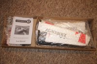
Unpacking the kit, you'll find everything neatly packaged in separate compartments. The kit did not come double-boxed, but the box is made of a very think and sturdy material and there was no damage to the box or the kit.
[h=2]Installing the motor box[/h]
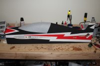
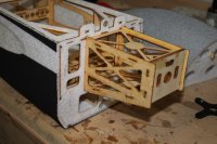
The first thing we need to do is to unpack the fuselage and locate the wooden motor box. The motor box attaches to the firewall (front of the fuse) by inserting the tabs on the motor box into the slots in the firewall. This may require a little bit of finagling, but you should not have to apply a lot of pressure. Doing so would damage the motor box.
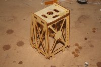
Once the motor box is firmly in place it's time to glue it to the firewall. The manual calls for foam safe CA, but we used regular thin CA, since EPP is resistant to most glue and thin CA wicks into the joints much better. We applied CA in all the joints and let it wick in. A thin spout for your CA bottle is invaluable when you do this!
[h=2]Installing the tail servos[/h]
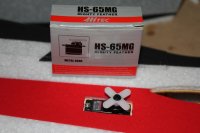
This step is very straightforward. Attach 9-12" extensions to the servo leads and secure them. Then route them through the servo slots and through the fuselage up to the cockpit area. Install the tail servos using the pre-drilled holes. These holes are a perfect match for a Hitec HS-65MG. Make sure you install the servos with the output shaft facing the tail of the plane.
[h=2]Installing the control horns[/h]
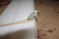
Install the control horns on each control surface. You probably need to clean out the slots a bit using a hobby knife. Lightly sand the sides of the surfaces to make a better glue bond. Insert the horns and make sure they curve toward the hinge line as shown below. Push the horns all the way in and secure with thin CA. Let the CA wick into the slot and keep dropping CA until it doesn't wick into the joint anymore. Do this to the rudder, elevator and ailerons. Make sure you install the horns on the correct side of the surface! The rudder horn should attach to the left side of the rudder and the elevator horn should be attached to the bottom of the right elevator half.
[h=2]Assembling and installing the main gear[/h]
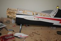
Locate the axles and slide on the wheels on the non-threaded end. Slide on the collar and tighten. Make sure to apply a drop of thread locker before tightening the set screw. Then push the threaded end through the slot in the wheel pant and pop the other end through the small hole in the wheel pant. You may have to bend and stretch the pant a little, but that's OK since it's EPP. Install the wheel and pant on the strut and tighten the lock nut. Tighten it just enough to squeeze the pant to the strut without damaging it.
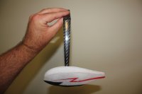
IMPORTANT: Make sure you install the wheels so the "flat" side of the strut is facing forward as shown in this picture.
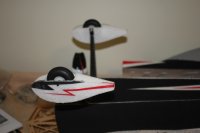
Attach the gear assembly to the bottom of the fuselage using the supplied screws as shown.
[h=2]Assembling the wings[/h]
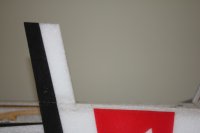
Locate the wing root tips. These are the small rectangular pieces that attach near the root of the wing. The manual calls for CA, but since it makes a brittle bond, we like a urethane cement, such as Welder's. For our build, we used Goop, which has similar characteristics. Apply the glue to each side of the bond (or one side, attach, then separate), wait 5-10 minutes and join the pieces. You should have an immediate bond.
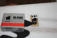
Next, install the servos. If you are using HS-65MGs, we recommend that you don't attach any extensions at this point. The stock servo leads will be long enough to reach through the hole in the wing root. On our plane, we needed to enlarge the servo openings by about 1mm lengthwise to make the servos fit.
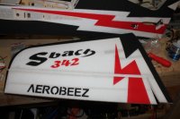
Finally, install the servo horns on the ailerons in the same we you did with the tail surfaces, and attach the ailerons to the wings. You may need to clean the slots for the hinges with a hobby knife before inserting the hinges. Make sure you have a tight hinge joint, while still allowing full movement of the aileron. Once you are satisfied with the hinge gap, secure each hinge with two drops of thin CA (not foam safe). Make sure the CA wicks into the hinge. Let dry for a minute, then turn over the wing and repeat the process.
[h=2]Installing the horizontal stabilizer[/h]
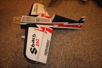
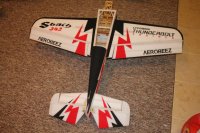
Temporarily install the main wings and secure with the supplied rubber band. Slide the elevator through the slot in the rear of the fuselage. Slide the horizontal stabilizer through the slot and insert the elevator hinges into the stabilizer but do not glue them yet. Measure from the tip of the stabilizer to the fuselage and adjust until the distance is equal on both sides. Then measure from the tip of the stabilizer to the tip of the main wings. Adjust to make the distance equal on both sides. Verify that the distance from the stabilizer tip to the fuselage is still equal on both sides. When you are satisfied, apply thin CA (not foam safe) to the joint between the stabilizer and the fuselage. Let it wick in and dry. Flip the plane upside down and repeat the process. Finally, secure the hinges the same way you did with the ailerons.
[h=2]Installing the rudder[/h]
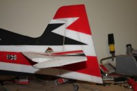
Another easy step! Clean the hinge slots with a hobby knife and slide in the rudder hinge. Glue in place the same way you did with the ailerons. Make sure you use thin CA!
[h=2]Installing the push rods[/h]
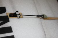
Locate the longest servo arms in the package that came with the servo. If you are using the Hitec HS65MG, the longest arm will provide you with perfect throws. Don't install it on the servo yet. Widen the outermost hole using a 5/64" drill bit and install the pushrod using the supplied nut. Make sure to install one washer on each side of the servo arm. Tighten the nut just enough to provide a snug fit, while just loose enough that the pushrod connector can still spin freely. Secure the nut with a small drop of thin CA. Let wick in for a few seconds, then hit with kicker.
Attach a ball-joint connector to the end of each of the supplied carbon-fiber pushrod as follows: Apply a small drop of thin CA into the opening of the plastic part of the ball-joint connector then quickly insert the end of the carbon-fiber pushrod into the opening. You should have a tight bond within a second or two.
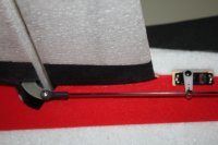
Install the ball-joint in the hole on the control horn that is the closest to the control surfaces (if you want crazy throws and we know you do). Slide the pushrod through the connector on the servo arm and install the servo arm on the servo. Adjust so that the arm and the pushrod are at a 90 degree angle when the control surface is in neutral position and tighten the set screw on the pushrod connector.
[h=2]Installing the power system and radio[/h]
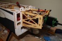
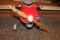
For this build, we're using a SunnySky 2820 920Kv motor from EP Buddy and a ZTW Gecko 65A ESC from Altitude Hobbies. The kit does not come with any pre-drilled holes or blind nuts. We used the X-mount as a drill template and secured the motor with 6-32 screws and nylon lock nuts. Don't forget to install large washers on the inside of the firewall. Depending on your motor, you may have to install standoffs to get the right spinner gap. If you get the SunnySky, however, the length of the motor will match perfectly without any standoffs.
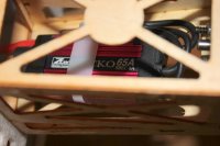
The ESC has to be installed inside the motor box, or the cowl won't fit. If possible, try to route the wires so the connectors are as far from each other as possible, to eliminate the risk of a short. We used a heavy-duty cable tie to secure the ESC.
Pop out the excess foam from the air intakes and motor compartment on the cowl and install the cowl. Carefully slide the tabs into the slots and press down to secure it. The cowl is held in place with the tabs and magnets and no screws are required. You may have to clean out the slots in the firewall with a hobby knife before installing the cowl.
Install the prop and a spinner (if desired).
[h=2]Radio installation[/h]
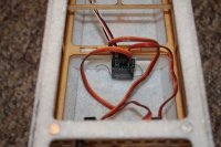
We attached the receiver to the former near the middle of the cockpit and with the bottom part of the receiver resting on the cockpit floor. There are no immediate obstacles to the signal path in this position.
[h=2]Servo settings, CG and final touches[/h]
Now it's time to set up the servos and GC. Set all trims and sub-trims to zero on your radio and unscrew all the servo arms. Power up the plane, bind the radio and wait for all the servos to center. With the servos centered, put all the servo arms back and make sure the control surfaces are as close to their neutral position as possible. Adjust the pushrod length first, and then fine tune using your sub trim. Don't forget to make sure no controls are reversed.
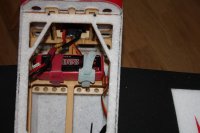
The manual calls for a CG of 4 3/4" - 5 3/4" behind the leading edge at the wing root. This comes out to about 1/4" in front of the wing spar to 3/4" behind the wing spar. For the maiden, we're setting it up to balance on the wing tube. To achieve this GC, we installed our 2200mAh battery sideways on the battery tray as shown below. The kit comes with a Velcro strap, but we installed an extra strap for extra safety.
UPDATE: After publishing this article, a representative from Aerobeez contacted us and made the following remarks:
* In order to make sure the plane isn't tail heavy, you want your motor and ESC to weigh at least 200g. A lighter power system will result in a tail heavy plane that is going to be difficult to balance. Our SunnySky motor weighs 140g and the weights 74g, which makes it balance really well.
* Although the battery was mounted sideways in the build thread, it is possible to mount it longitudally and to push it into the motor box to add some more nose weight.
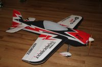
Now this beauty is ready for its maiden flight!
3DRCForums.com recently acquired an Aerobeez 48" EPP/Balsa Sbach 342. Our review of this airplane will consist of two parts. Part one will be a build thread mainly focusing on the build techniques and part two will feature a review of the quality of the kit and the flying characteristics. As you will see, this is a very easy and straightforward build.
[h=1]Let's begin the build![/h]
Unpacking the kit, you'll find everything neatly packaged in separate compartments. The kit did not come double-boxed, but the box is made of a very think and sturdy material and there was no damage to the box or the kit.

[h=2]Installing the motor box[/h]
The first thing we need to do is to unpack the fuselage and locate the wooden motor box. The motor box attaches to the firewall (front of the fuse) by inserting the tabs on the motor box into the slots in the firewall. This may require a little bit of finagling, but you should not have to apply a lot of pressure. Doing so would damage the motor box.


Once the motor box is firmly in place it's time to glue it to the firewall. The manual calls for foam safe CA, but we used regular thin CA, since EPP is resistant to most glue and thin CA wicks into the joints much better. We applied CA in all the joints and let it wick in. A thin spout for your CA bottle is invaluable when you do this!

[h=2]Installing the tail servos[/h]
This step is very straightforward. Attach 9-12" extensions to the servo leads and secure them. Then route them through the servo slots and through the fuselage up to the cockpit area. Install the tail servos using the pre-drilled holes. These holes are a perfect match for a Hitec HS-65MG. Make sure you install the servos with the output shaft facing the tail of the plane.

[h=2]Installing the control horns[/h]
Install the control horns on each control surface. You probably need to clean out the slots a bit using a hobby knife. Lightly sand the sides of the surfaces to make a better glue bond. Insert the horns and make sure they curve toward the hinge line as shown below. Push the horns all the way in and secure with thin CA. Let the CA wick into the slot and keep dropping CA until it doesn't wick into the joint anymore. Do this to the rudder, elevator and ailerons. Make sure you install the horns on the correct side of the surface! The rudder horn should attach to the left side of the rudder and the elevator horn should be attached to the bottom of the right elevator half.

[h=2]Assembling and installing the main gear[/h]
Locate the axles and slide on the wheels on the non-threaded end. Slide on the collar and tighten. Make sure to apply a drop of thread locker before tightening the set screw. Then push the threaded end through the slot in the wheel pant and pop the other end through the small hole in the wheel pant. You may have to bend and stretch the pant a little, but that's OK since it's EPP. Install the wheel and pant on the strut and tighten the lock nut. Tighten it just enough to squeeze the pant to the strut without damaging it.
IMPORTANT: Make sure you install the wheels so the "flat" side of the strut is facing forward as shown in this picture.

Attach the gear assembly to the bottom of the fuselage using the supplied screws as shown.


[h=2]Assembling the wings[/h]
Locate the wing root tips. These are the small rectangular pieces that attach near the root of the wing. The manual calls for CA, but since it makes a brittle bond, we like a urethane cement, such as Welder's. For our build, we used Goop, which has similar characteristics. Apply the glue to each side of the bond (or one side, attach, then separate), wait 5-10 minutes and join the pieces. You should have an immediate bond.

Next, install the servos. If you are using HS-65MGs, we recommend that you don't attach any extensions at this point. The stock servo leads will be long enough to reach through the hole in the wing root. On our plane, we needed to enlarge the servo openings by about 1mm lengthwise to make the servos fit.

Finally, install the servo horns on the ailerons in the same we you did with the tail surfaces, and attach the ailerons to the wings. You may need to clean the slots for the hinges with a hobby knife before inserting the hinges. Make sure you have a tight hinge joint, while still allowing full movement of the aileron. Once you are satisfied with the hinge gap, secure each hinge with two drops of thin CA (not foam safe). Make sure the CA wicks into the hinge. Let dry for a minute, then turn over the wing and repeat the process.

[h=2]Installing the horizontal stabilizer[/h]
Temporarily install the main wings and secure with the supplied rubber band. Slide the elevator through the slot in the rear of the fuselage. Slide the horizontal stabilizer through the slot and insert the elevator hinges into the stabilizer but do not glue them yet. Measure from the tip of the stabilizer to the fuselage and adjust until the distance is equal on both sides. Then measure from the tip of the stabilizer to the tip of the main wings. Adjust to make the distance equal on both sides. Verify that the distance from the stabilizer tip to the fuselage is still equal on both sides. When you are satisfied, apply thin CA (not foam safe) to the joint between the stabilizer and the fuselage. Let it wick in and dry. Flip the plane upside down and repeat the process. Finally, secure the hinges the same way you did with the ailerons.


[h=2]Installing the rudder[/h]
Another easy step! Clean the hinge slots with a hobby knife and slide in the rudder hinge. Glue in place the same way you did with the ailerons. Make sure you use thin CA!

[h=2]Installing the push rods[/h]
Locate the longest servo arms in the package that came with the servo. If you are using the Hitec HS65MG, the longest arm will provide you with perfect throws. Don't install it on the servo yet. Widen the outermost hole using a 5/64" drill bit and install the pushrod using the supplied nut. Make sure to install one washer on each side of the servo arm. Tighten the nut just enough to provide a snug fit, while just loose enough that the pushrod connector can still spin freely. Secure the nut with a small drop of thin CA. Let wick in for a few seconds, then hit with kicker.
Attach a ball-joint connector to the end of each of the supplied carbon-fiber pushrod as follows: Apply a small drop of thin CA into the opening of the plastic part of the ball-joint connector then quickly insert the end of the carbon-fiber pushrod into the opening. You should have a tight bond within a second or two.
Install the ball-joint in the hole on the control horn that is the closest to the control surfaces (if you want crazy throws and we know you do). Slide the pushrod through the connector on the servo arm and install the servo arm on the servo. Adjust so that the arm and the pushrod are at a 90 degree angle when the control surface is in neutral position and tighten the set screw on the pushrod connector.


[h=2]Installing the power system and radio[/h]
For this build, we're using a SunnySky 2820 920Kv motor from EP Buddy and a ZTW Gecko 65A ESC from Altitude Hobbies. The kit does not come with any pre-drilled holes or blind nuts. We used the X-mount as a drill template and secured the motor with 6-32 screws and nylon lock nuts. Don't forget to install large washers on the inside of the firewall. Depending on your motor, you may have to install standoffs to get the right spinner gap. If you get the SunnySky, however, the length of the motor will match perfectly without any standoffs.
The ESC has to be installed inside the motor box, or the cowl won't fit. If possible, try to route the wires so the connectors are as far from each other as possible, to eliminate the risk of a short. We used a heavy-duty cable tie to secure the ESC.


Pop out the excess foam from the air intakes and motor compartment on the cowl and install the cowl. Carefully slide the tabs into the slots and press down to secure it. The cowl is held in place with the tabs and magnets and no screws are required. You may have to clean out the slots in the firewall with a hobby knife before installing the cowl.
Install the prop and a spinner (if desired).

[h=2]Radio installation[/h]
We attached the receiver to the former near the middle of the cockpit and with the bottom part of the receiver resting on the cockpit floor. There are no immediate obstacles to the signal path in this position.

[h=2]Servo settings, CG and final touches[/h]
Now it's time to set up the servos and GC. Set all trims and sub-trims to zero on your radio and unscrew all the servo arms. Power up the plane, bind the radio and wait for all the servos to center. With the servos centered, put all the servo arms back and make sure the control surfaces are as close to their neutral position as possible. Adjust the pushrod length first, and then fine tune using your sub trim. Don't forget to make sure no controls are reversed.
The manual calls for a CG of 4 3/4" - 5 3/4" behind the leading edge at the wing root. This comes out to about 1/4" in front of the wing spar to 3/4" behind the wing spar. For the maiden, we're setting it up to balance on the wing tube. To achieve this GC, we installed our 2200mAh battery sideways on the battery tray as shown below. The kit comes with a Velcro strap, but we installed an extra strap for extra safety.

UPDATE: After publishing this article, a representative from Aerobeez contacted us and made the following remarks:
* In order to make sure the plane isn't tail heavy, you want your motor and ESC to weigh at least 200g. A lighter power system will result in a tail heavy plane that is going to be difficult to balance. Our SunnySky motor weighs 140g and the weights 74g, which makes it balance really well.
* Although the battery was mounted sideways in the build thread, it is possible to mount it longitudally and to push it into the motor box to add some more nose weight.
Now this beauty is ready for its maiden flight!

Last edited by a moderator:
