Orelelbaz6
30cc
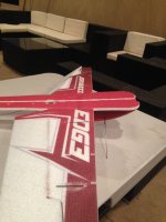
Hey Guys! Aerobeez has just came out with a bunch of new airplanes including the all new 32" Epp Edge!
My setup will be:
-Turnigy 2204-14t
-Turnigy 12amp esc
-GWS 8x4.3
- Hitec HS-56 for Ailerons
- Futaba s3114 on tail (I ordered HS-45s to use but they did not come in yet in time for the build)
-TP 325mah 3s
(NOTE: For Epp i recommend using the glue that is supplied with the kit. Although it might seem like it drys fast, i recommend allowing it to sit for a couple of hours before it is fully cured)


I like to lay everything out on the table before i begin to make sure i have everything. Aerobeez supply's everything you need to complete the airframe all the way from the carbon fiber re-enforcement to the special glue needed to glue together the Epp parts.


First off, locate your horizontal fuse piece. Now you want to gently push out where the tabs will be going through. Every thing is laser cut so a knife is not needed, your finger should do the trick, just push them
through!

Now repeat this step on the elevator and wings. The elevator only has one little tab in the front and the wings have 4 tabs each towards the end of them, these tabs are for your side-force generators, if you do not want to fly with side force generators than i suggest you do not remove the tabs in the wing.


Now you can line up the wings and elevators to fuselage to make sure everything fits correctly. The connections are directional, so there are only one way the wings and elevator can be glued onto the fuselage.

Now before we stat gluing anything i like to lay down a piece on wax paper, this is so i do not get the table dirty but more importantly so that the pieces when glued together don't get stuck to the table.

Press the horizontal stabilizer to the fuselage and mark on both ends where the connections end. This will help you when gluing.

Using the marks we made as a guideline, run a thin bead of glue where the horizontal stabilizer and the fuselage meet each other with the glue that comes in the kit. CA is not recommended for this step.


With a dry piece of paper towel, clean the excess glue that will seep out of the connections on both sides.


Now if you are patient you can wait a couple hours and allow the glue to dry before moving onto the next step, but if you are like me and are supper needy to get flying you can use some masking tape to tape the 2 pieces together to hold them from separating so you can begin the next step.


Now using the same steps we used to glue the elevator glue the wings together. Be very careful when gluing the wings, not to put any glue on the aileron part of the wing, that will be very hard and messy to remove later.


Next locate your carbon fiber strips and remove the square carbon fiber rod and move the rest of the rods aside for later.

Test fit the carbon rod in the slot and make sure its fits nice and snug.


To make sure i don't get glue on anything that doesn't need it i like to mask off the sides of the slot so that nothing gets messy.

Carefully go down the slot with a thin bead of glue, you don't need to over do it because the glue is very thick.

Now once you put glue in the slot, you may place your carbon rod. I like to start pushing in from the edge and work my way down.

Once the rod is in you may wipe away the excess glue.

While the glue is still wet, remove the masking tape. This will insure that the tape does not get glued to the plane.

With the tape removed lightly clean the area over the rod again. Do not wipe to hard or the paint on the plane will fade.

Going down the wing put some masking tape tightly crossing the wing spar in order to keep the wing spar from coming out.

At his point allow your plane to dry for about 2 hours before moving to the next step.

Now locate the bottom part of the fuselage.


Test fit the fuse piece on the bottom of the plane. Remove any piece of masking tape that prohibits the pieces from fitting.

Make sure the pieces fit flush and square all the way through the plane.


Run a thin bead of glue going through the center line of the plane.

Now place the bottom part of the fuse on the plane. I like to start from the nose and move my way down to the tail.

Once the fuse is glued wipe away any excess glue.


As the glue is drying make sure the fuse is square and strait. I used a few servo boxes to help me keep the plane square. At this point allow the plane to dry for another 1-2 hours.

Once the plane is dry, you can remove all masking that has been done to the plane.

Now locate your landing gear pieces. They are the 2 flat pieces of carbon that come in the kit.

Now poke out the slot in the fuse that is men for the landing gears, slide the carbon piece through and stick the carbon in the slot in the horizontal nose of the plane that has an arrow above it.

Slide in the other rod and repeat the last step.

Using CA, glue together the carbon rods where they cross. Do not glue them to the foam with the CA!


Using the glue that comes with the kit, tack some glue where the carbon meets the foam.

Make sure the plane is still square and allow the landing gear to dry.
My setup will be:
-Turnigy 2204-14t
-Turnigy 12amp esc
-GWS 8x4.3
- Hitec HS-56 for Ailerons
- Futaba s3114 on tail (I ordered HS-45s to use but they did not come in yet in time for the build)
-TP 325mah 3s
(NOTE: For Epp i recommend using the glue that is supplied with the kit. Although it might seem like it drys fast, i recommend allowing it to sit for a couple of hours before it is fully cured)
I like to lay everything out on the table before i begin to make sure i have everything. Aerobeez supply's everything you need to complete the airframe all the way from the carbon fiber re-enforcement to the special glue needed to glue together the Epp parts.
First off, locate your horizontal fuse piece. Now you want to gently push out where the tabs will be going through. Every thing is laser cut so a knife is not needed, your finger should do the trick, just push them
through!
Now repeat this step on the elevator and wings. The elevator only has one little tab in the front and the wings have 4 tabs each towards the end of them, these tabs are for your side-force generators, if you do not want to fly with side force generators than i suggest you do not remove the tabs in the wing.
Now you can line up the wings and elevators to fuselage to make sure everything fits correctly. The connections are directional, so there are only one way the wings and elevator can be glued onto the fuselage.
Now before we stat gluing anything i like to lay down a piece on wax paper, this is so i do not get the table dirty but more importantly so that the pieces when glued together don't get stuck to the table.
Press the horizontal stabilizer to the fuselage and mark on both ends where the connections end. This will help you when gluing.
Using the marks we made as a guideline, run a thin bead of glue where the horizontal stabilizer and the fuselage meet each other with the glue that comes in the kit. CA is not recommended for this step.
With a dry piece of paper towel, clean the excess glue that will seep out of the connections on both sides.
Now if you are patient you can wait a couple hours and allow the glue to dry before moving onto the next step, but if you are like me and are supper needy to get flying you can use some masking tape to tape the 2 pieces together to hold them from separating so you can begin the next step.
Now using the same steps we used to glue the elevator glue the wings together. Be very careful when gluing the wings, not to put any glue on the aileron part of the wing, that will be very hard and messy to remove later.
Next locate your carbon fiber strips and remove the square carbon fiber rod and move the rest of the rods aside for later.
Test fit the carbon rod in the slot and make sure its fits nice and snug.
To make sure i don't get glue on anything that doesn't need it i like to mask off the sides of the slot so that nothing gets messy.
Carefully go down the slot with a thin bead of glue, you don't need to over do it because the glue is very thick.
Now once you put glue in the slot, you may place your carbon rod. I like to start pushing in from the edge and work my way down.
Once the rod is in you may wipe away the excess glue.
While the glue is still wet, remove the masking tape. This will insure that the tape does not get glued to the plane.
With the tape removed lightly clean the area over the rod again. Do not wipe to hard or the paint on the plane will fade.
Going down the wing put some masking tape tightly crossing the wing spar in order to keep the wing spar from coming out.
At his point allow your plane to dry for about 2 hours before moving to the next step.
Now locate the bottom part of the fuselage.
Test fit the fuse piece on the bottom of the plane. Remove any piece of masking tape that prohibits the pieces from fitting.
Make sure the pieces fit flush and square all the way through the plane.
Run a thin bead of glue going through the center line of the plane.
Now place the bottom part of the fuse on the plane. I like to start from the nose and move my way down to the tail.
Once the fuse is glued wipe away any excess glue.
As the glue is drying make sure the fuse is square and strait. I used a few servo boxes to help me keep the plane square. At this point allow the plane to dry for another 1-2 hours.
Once the plane is dry, you can remove all masking that has been done to the plane.
Now locate your landing gear pieces. They are the 2 flat pieces of carbon that come in the kit.
Now poke out the slot in the fuse that is men for the landing gears, slide the carbon piece through and stick the carbon in the slot in the horizontal nose of the plane that has an arrow above it.
Slide in the other rod and repeat the last step.
Using CA, glue together the carbon rods where they cross. Do not glue them to the foam with the CA!
Using the glue that comes with the kit, tack some glue where the carbon meets the foam.
Make sure the plane is still square and allow the landing gear to dry.
Last edited:


") ) Slide in your aileron servo and cut away any foam that prohibits you to do so.
) Slide in your aileron servo and cut away any foam that prohibits you to do so.