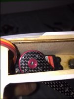
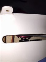
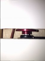
I have been building on this one for a couple of days now and have run into a possible problem. I am using the XQ 4020 servos and the supplied CF arms. I also purchased the aluminum wheels for these arms to fit to from Redwing. The problem arises when mounting the arm to the servo in the elevator halves. The slot cut out for the arms doesn't seem to be centered correctly and I can't get the arm to fit without potentially enlarging the slot. Can someone share if they may know a trick before I go cutting. Thanks.
You are using an out of date browser. It may not display this or other websites correctly.
You should upgrade or use an alternative browser.
You should upgrade or use an alternative browser.
50cc Slick 540 build issue (help!!!)
- Thread starter 3D Edge
- Start date
TimP
GSN Sponsor Tier 1
3d Edge,
What I did on a hatch install on the ailerons (and should apply here) is to but a notch our of the CF arm. just mark it where it meets the wood and then cut a rounded notch out at that point to give it a little more clearance.
Does this make sense? Or should I attach a drawing?
What I did on a hatch install on the ailerons (and should apply here) is to but a notch our of the CF arm. just mark it where it meets the wood and then cut a rounded notch out at that point to give it a little more clearance.
Does this make sense? Or should I attach a drawing?
TimP
GSN Sponsor Tier 1
Thank you for your email with the pictures. Rest assured we design RedwingRC aircraft to accommodate as many servo-arm combinations available as possible, and we don't think this is a design flaw of the plane, but rather just a slightly incompatible combination of equipment/mounting. It's likely one of our Miracle arms would fit without any trouble, as would an SWB or Spot-on. However, with the added depth of the carbon arm on top of the metal circular servo arm, it's just a little too far out of alignment. The best two recommended options to fix your issue:
1- Shave a little of the servo cutout from the side where the servo arm is touching. This will allow full freedom of movement.
2- Mount the carbon fiber servo arm underneath the metal servo wheel instead of on-top. You may need to open up the center hole slightly with a dremmel tool, to get it to slide over the spline socket.
Please let us know if this fixes your issue.
Regardless of what you say, it is a design flaw. I tried 3 different brands of servos and several different arms. I did have a small aluminum arm that fit with a hi-tec servo, but the arm still only had a 1/32" clearance. Both slots on both sides need to be pulled inboard 3/8" and this wouldn't be an issue with any combination of servo/arm. Overall the plane has gone together well and looks great with the exception of some minor covering discoloration on top of the fuselage near where the empennage starts.
SnowDog
Moderator
I've had to modify servo cutout holes on many models from many manufacturers. No big deal.
I certainly would not classify this as a design flaw.
Perhaps we might encourage Tim to enlarge the cutout holes on future airframes so that more combinations of hardware could be supported without requiring even minor modifications?
I certainly would not classify this as a design flaw.
Perhaps we might encourage Tim to enlarge the cutout holes on future airframes so that more combinations of hardware could be supported without requiring even minor modifications?
cardenflyer
70cc twin V2
I've had to enlarge the slot on 3dhs extreme flight redwing and others. That's pretty common. This isn't anything compared to what someone I know is going through with another brand mounting a motor. Got to remember that Redwing doesn't build each one. They all will need minor work to make it right. No matter what.
I even think in the extreme flight 104 extra build they tell you this will need to be done.
I even think in the extreme flight 104 extra build they tell you this will need to be done.
Last edited by a moderator: