• If you are new to GiantScaleNews.com, please register, introduce yourself, and make yourself at home.

    We're 1st in Giant Scale RC because we've got the best membership on the internet! Take a look around and don't forget to register to get all of the benefits of GSN membership!

    Welcome!
  • Unless you are a paid advertiser NO more posting advertisement in the individual vendor forums. You may post in the Manufacturer's Announcements section only but only ONCE a month unless your a paid advertiser.

3DHS 84" Bigfoot Build Log

SnowDog

Moderator
Hey guys, I'm starting a build log for my Bigfoot. I'm going to follow the manual as closely as possible but I'm also going to highlight changes/updates based on this build and other builds that have already been completed.


This plane will be getting an OS GT33 for power.


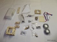
So let's start with some basic pictures of the unpacked box:

DSCF0958.jpg DSCF0962.jpg

As usual the double box shipping box saved my model from the UPS "Hulk" drivers ("Hulk smash"!) ;)
Not that bad really, one corner of the box was slightly dented; no damage inside!
 
Last edited by a moderator:

SnowDog

Moderator
I do have some recent progress!...just need to find time to update the build log and post some pics.
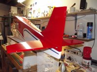
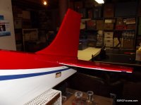
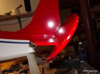
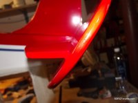
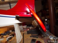
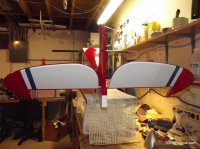
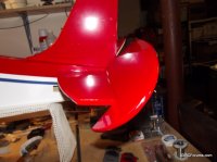
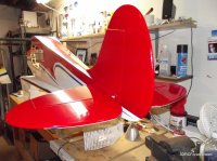
tail surfaces are finished without any trouble.
Working on aileron and flap servos tonight and mounting the engine tomorrow night.
 

SnowDog

Moderator
Did some digging around regarding engine standoffs...since I'm installing the OS GT33, I needed to know the length of the standoff required. Per Noll,

1.5 inch standoffs for the OS 33 GT.

Firewall to front of cowl measures 6 1/8 inches.

The cowl is mounted with four wood screws, similar to our other 30cc airframes so some adjustment can be made.
 

SnowDog

Moderator
more progress on Bigfoot...still working on the basics that are familiar to any 3DHS airframe build.

DSCF0973.jpg DSCF0974.jpg
DSCF0975.jpg DSCF0976.jpg
DSCF0977.jpg DSCF0978.jpg
DSCF0979.jpg DSCF0980.jpg

No surprises here. Even though the manual suggests to mount the gear and fairings as the first step, I decided to defer installation of the gear and fairings until later in the build. I've heard that the fairings get banged around during the build and I wanted to save them the abuse of my build table.

The tail surfaces installed straight and true; no sanding was necessary.

The next step will be installing the tail servos, running the wires, and installing the control linkages.
 
Last edited by a moderator:

SnowDog

Moderator
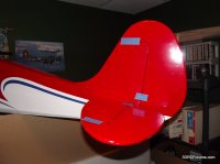
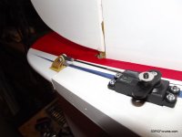
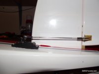
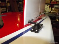
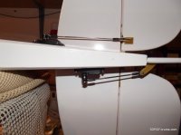
Still digging out from the backlog...here are some more pics...this time the servos and linkage instalation on the tail surfaces:


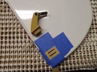
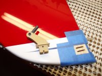
thought I would try out the tape around the control horn technique.
It does work well...but don't let the epoxy set fully before removing it. ;)
DSCF0984.jpg DSCF0989.jpg

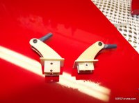
this was an oddity...one set of control horns had a shorter base length.?
DSCF0994.jpg

everything is taped, aligned, and glued.
DSCF0995.jpg

finished installing the rudder linkage and servo. Servo in the tail because this is a gasser. :)
don't need much length on the servo arm to get full travel on the rudder.
DSCF0998.JPG
I do prefer to use my own mounting hardware (socket cap screws with built-in washer) instead of the stock phillips head screws; the head on those screws is just too soft and once screwed in, I always seem to strip them when I need to uninstall them. Socket head washer screws from trimcraftaviationrc.com work really well and are a really good value.

elevator servo linkage worked just fine.
DSCF0999.jpg

I did have to cut off a small amount on the threaded rod for both the rudder and the elevator...they were both too long by at least 1/4 inch.
DSCF1001.jpg DSCF1002.jpg

next step on the tail: support wires and tail wheel...stay tuned.
 
Last edited by a moderator:

SnowDog

Moderator
Well I'm all caught up with pictures, except that I did more work tonight, so I'm posting this pics now so I can stay on track! Tonight I decided I was going to install the aileron and flap servos in both wings. I didn't realize at the time what an aggressive goal that was! I work slow and steady, always try to check things twice or three times before I glue or cut, so this step took a while.

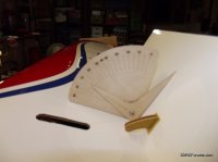
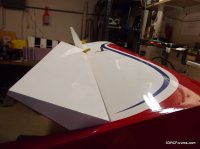
checking the aileron and flap deflection:
DSCF1016.jpg

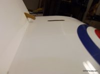
trial fit control horns and check travel. Seems to be plenty of clearance for both aileron and flap:
DSCF1019.jpg

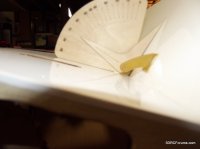
after reading the manual completely before starting the build (everyone does this, right?) I discovered that the manual states two different values for desired flap deflection. 70-75% is the max flap deflection based on the latter section of the manual and community knowledge.
DSCF1015.jpg DSCF1013.jpg

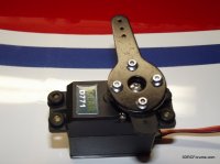
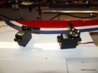
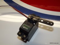
1.5" servo arms are installed on the aileron and flap servos in order reach above the surface of the wing from the pocket into which the servos are installed:
DSCF1008.jpg DSCF1011.jpg DSCF1003.jpg

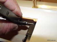
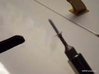
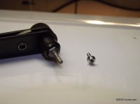
I must say that a recent trip to Harbor Freight yielded a great tool which was very handy during this step:
DSCF1023.jpg DSCF1026.jpg DSCF1029.jpg DSCF1028.jpg
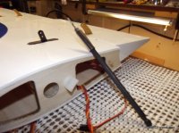
as I mentioned I prefer the socket washer head screws for the servos and other similar applications. The rachet tool proved to be indispensable during this step, as was the hex extension shaft which made it very easy to install the flap servo.

one item to note: the string which is in place to allow the servo wire from the aileron servo to be routed to the wing root was threaded directly through the space where the flap servo is to be installed. It was no big deal to thread the string around the flap servo opening, but it is worth noting. This is something that should be addressed as a build issue for future production runs of the product.

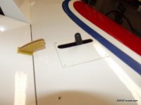
Here is one aileron servo installed and cover attached:
DSCF1018.jpg
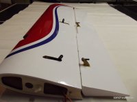
okay a good bit of work, but one wing is done!
DSCF1030.jpg

fast forward an hour or so....and...
DSCF1031.jpg

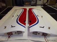
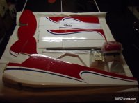
both wings are done, control horns are glued in, and waiting for the epoxy to dry.
 
Top