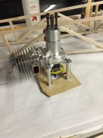
• If you are new to GiantScaleNews.com, please register, introduce yourself, and make yourself at home.

    We're 1st in Giant Scale RC because we've got the best membership on the internet! Take a look around and don't forget to register to get all of the benefits of GSN membership!

    Welcome!

Sport 30% Edge 540 Pete Marshall Plans with Laser Cut Short Kit

Bluepilot2003

70cc twin V2
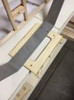
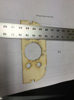
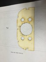
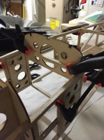
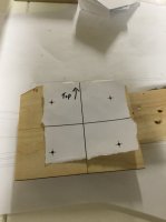
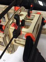
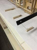
I got some good work done today. I started off by drilling the new holes in the landing gear plate since the EF gear holes didn't line up. Next, I used a spare piece of plywood to cover the hole in F-1 that would have been used for a canister or tuned pipe.

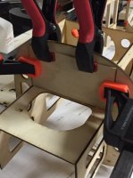
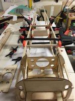
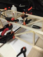
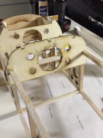
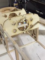
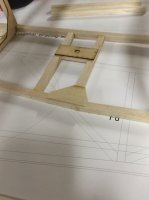
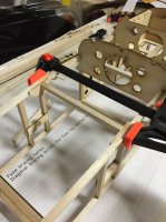
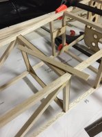
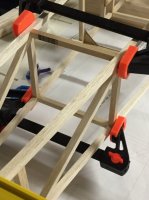
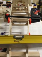
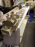
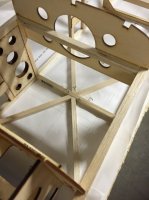
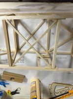
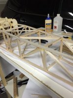
Soon to follow, the F-5 and F-3 framework was glued in. Everything is still looking perfectly square as far as I can tell.
 

Attachments

  • image.jpg
    image.jpg
    42 KB · Views: 234
  • image.jpg
    image.jpg
    47.1 KB · Views: 257
  • image.jpg
    image.jpg
    65.6 KB · Views: 247
  • image.jpg
    image.jpg
    52.1 KB · Views: 435

Bluepilot2003

70cc twin V2
Now, I took the time to fix my issue with the F-3 former. As you can see from the picture, it was quite a bit wider than the top down plans show. So I lined up where the former needed to go on the plans and used a straight edge to mark where the inside part of the stringer runs. Then I cut out the grooves for the stringers to match the new lines I drew.

The former was then put into the frame to mark where I needed to hack off the extra wood on the sides. I cut off the sides and glued it in. I will sand it to a little better shape and fit later.
 

Attachments

  • image.jpg
    image.jpg
    34.7 KB · Views: 233
  • image.jpg
    image.jpg
    28.3 KB · Views: 259
  • image.jpg
    image.jpg
    46.9 KB · Views: 267
  • image.jpg
    image.jpg
    47.2 KB · Views: 292
  • image.jpg
    image.jpg
    56.6 KB · Views: 239
Now, I took the time to fix my issue with the F-3 former. As you can see from the picture, it was quite a bit wider than the top down plans show. So I lined up where the former needed to go on the plans and used a straight edge to mark where the inside part of the stringer runs. Then I cut out the grooves for the stringers to match the new lines I drew.

The former was then put into the frame to mark where I needed to hack off the extra wood on the sides. I cut off the sides and glued it in. I will sand it to a little better shape and fit later.

Yup, I just looked at my CAD file and sure enough it's a bit too wide. I have fixed it on my laser file. Good Catch!
 

Bluepilot2003

70cc twin V2
I did the support pieces first yesterday. I just used some spare 1/8 plywood to make the two pieces. After that, I placed the cross braces in the F-4 area.

When I glued in the F-5 cross section, I noticed the other side wasn't flush with the long stringers. I fixed that with a 3/32" balsa sheeting cut to size.

After that, I worked on the firewall. I used the DA-50 drilling guide from the EF website to drill the holes. I mounted the engine to see where I should mount the firewall to the airframe. I am going to move the firewall slightly forward of the location on the plans to get the location I need.

I cut the top part of the motor box to have the correct right thrust built into the airframe so I don't need to set that later. Then I glued it into place with medium CA.

Then, I went back to the plans and cut the rest of the cross pieces while everything was drying.

Right before I went to bed, I glued in the F-6 cross braces.
 

Attachments

  • image.jpg
    image.jpg
    32.4 KB · Views: 235
  • image.jpg
    image.jpg
    57.8 KB · Views: 249
  • image.jpg
    image.jpg
    35.6 KB · Views: 235
  • image.jpg
    image.jpg
    53.2 KB · Views: 242
  • image.jpg
    image.jpg
    57.6 KB · Views: 246
  • image.jpg
    image.jpg
    28.5 KB · Views: 245
  • image.jpg
    image.jpg
    49.2 KB · Views: 267
  • image.jpg
    image.jpg
    51.5 KB · Views: 251
  • image.jpg
    image.jpg
    37.8 KB · Views: 238
  • image.jpg
    image.jpg
    51.4 KB · Views: 270
  • image.jpg
    image.jpg
    50.1 KB · Views: 239

Bluepilot2003

70cc twin V2
After last night, I can see a little bit of lopsidedness starting to show. After further examination, one side stringer is a way harder balsa than the other side.

With that in mind, I placed the fuselage upside down flat on the board on top of the plans and pinned it down. Then I wet the hard side to hopefully shape it properly. We will see how that fares...

With it pinned down, I glued in the cross braces at F-8.
 

Attachments

  • image.jpg
    image.jpg
    58.9 KB · Views: 256
  • image.jpg
    image.jpg
    50.4 KB · Views: 252

Bluepilot2003

70cc twin V2
So I should have just done the whole fuselage on the plans like I am now before putting the motor box on. That would have guaranteed a straight fuselage from the get go with no worries of warping.

I did a good portion of the diagonal bracing tonight. I don't know how much longer it would have taken without the little hobby hack saw. That was a good investment for this build! Nothing crazy for here. But since these are very hard to clamp well, I used CA to put these in.
 

Attachments

  • image.jpg
    image.jpg
    35.4 KB · Views: 244
  • image.jpg
    image.jpg
    48.5 KB · Views: 240
  • image.jpg
    image.jpg
    54.1 KB · Views: 278
  • image.jpg
    image.jpg
    53.1 KB · Views: 235

BalsaDust

Moderator
nothing wrong with CA. I believe most of the fuse structure on the Vipers that Terryscustom has been building are glued together with CA. My last couple of profiles have been completely glued together with CA minus the tube and motor mount area that get epoxy.
 

Bluepilot2003

70cc twin V2
This is actually the first time I have built a plane using wood glue at all. I've been exclusively epoxy and CA. I just didn't want to sell the farm to buy glue this time around!
 

49dimes

Damn I'm hungry
There are pluses to using the wood glue. Especially in areas that have a lot of surface. I have had CA joints "pop" before. I think it is more of the "CA Wedge" cracking due to a less quality joint fit that did not allow the full "wicking action". Wood glue and its flexing properties would be able to resist a poor fitting joint from failing a little better IMO.
 
Top