GSNadmin
Staff member
There’s an old saying that says “scale models are really never finished, you just stop adding details to them”! Each modeler has to decide for himself when enough is enough. For me, I enjoy adding medium easy to see details to the top surfaces of the wings and control surfaces and in particular I add dummy control linkages. To take care of the flying demands of the plane, the RC linkages are on the underside. The delicate control surfaces that take care of the model’s appearance only have to look good to do their jobs! And these little bits and pieces all add up to an impressive static and craftsmanship score at the end of the day.

Here’s the finished wing of the Howard Ike complete with rib stitching and the big Chevrolet Logo in place. But the wing still looks plane-jane! How about some scale control linkages to go with the ailerons?
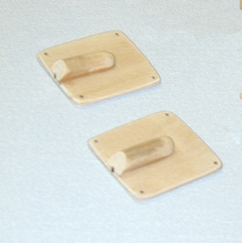
Start by making some panel molds to vacuum-form the access panels. These are nothing more than some squares of 1/16-inch plywood with a split dowel glued to them to form the cable exit. Only one is needed but I made two.
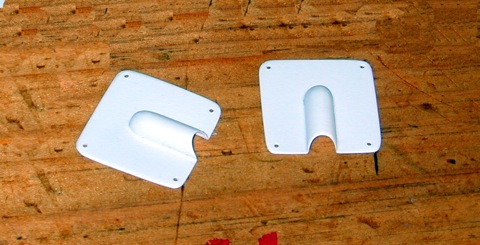
Placed on a home-made vacuum-forming box, I made these plastic linkage covers from 0.020-inch styrene sheet. While I was at it, I also made pushrod exit covers to help doll up the other RC linkages on the model, but that’s another story!
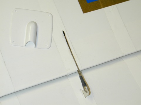
The fake aileron linkage is nothing more than some braded cable (control-line variety) about 0.025-inch in diameter. The small control horn is made from 0.060-inch sheet plastic. It is inserted into a slit cutingto the aileron and attached with a drop of thin CA adhesive. To attach the cable simply form a loop and slip the cable into the hole in the control horn. To form the small cable-swage, I used a 3.8-inch long length of heat-shrink tubing. Shrink into place with a heat-gun and add a drop of thin CA to lock it into place. Attach the cable to the horn before installing the horn to the aileron.
The cable is about 4 inches long and it fits into a thin slot cut into the wing’s top surface. It isn’t attached to anything.
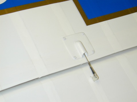
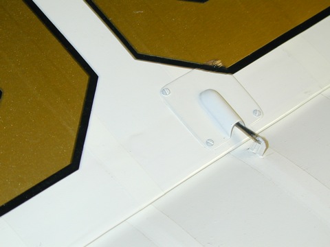
Here the linkage cover has been painted and screwed into place with small screws from microfasteners.com.
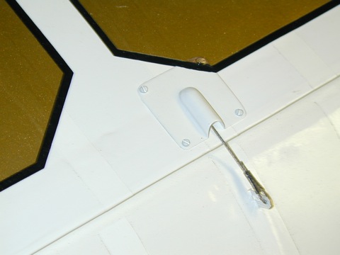
Here’s the cover from the other wing. Notice it has been painted to match up to the registration numbers applied to the right wing. Also note that the photos show the aileron in the full up and down position. You need to make sure the cable is long enough for the aileron’s full travel.
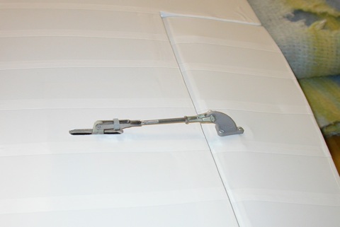
This is the RC linkage that’s under the aileron.

While you’re at it, cut a little bit of the left over sheet plastic and make some control tabs for the ailerons. These add a lot to the model’s overall scale appearance.
 http://www.modelairplanenews.com/wp-content/uploads/2016/02/MAN_Button_newsletter_WEB.jpg
Model Airplane News - The #1 resource for RC plane and helicopter enthusiasts featuring news, videos, product releases and tech tips.
Continue reading...
Here’s the finished wing of the Howard Ike complete with rib stitching and the big Chevrolet Logo in place. But the wing still looks plane-jane! How about some scale control linkages to go with the ailerons?
Start by making some panel molds to vacuum-form the access panels. These are nothing more than some squares of 1/16-inch plywood with a split dowel glued to them to form the cable exit. Only one is needed but I made two.
Placed on a home-made vacuum-forming box, I made these plastic linkage covers from 0.020-inch styrene sheet. While I was at it, I also made pushrod exit covers to help doll up the other RC linkages on the model, but that’s another story!
The fake aileron linkage is nothing more than some braded cable (control-line variety) about 0.025-inch in diameter. The small control horn is made from 0.060-inch sheet plastic. It is inserted into a slit cutingto the aileron and attached with a drop of thin CA adhesive. To attach the cable simply form a loop and slip the cable into the hole in the control horn. To form the small cable-swage, I used a 3.8-inch long length of heat-shrink tubing. Shrink into place with a heat-gun and add a drop of thin CA to lock it into place. Attach the cable to the horn before installing the horn to the aileron.
The cable is about 4 inches long and it fits into a thin slot cut into the wing’s top surface. It isn’t attached to anything.
Here the linkage cover has been painted and screwed into place with small screws from microfasteners.com.
Here’s the cover from the other wing. Notice it has been painted to match up to the registration numbers applied to the right wing. Also note that the photos show the aileron in the full up and down position. You need to make sure the cable is long enough for the aileron’s full travel.
This is the RC linkage that’s under the aileron.
While you’re at it, cut a little bit of the left over sheet plastic and make some control tabs for the ailerons. These add a lot to the model’s overall scale appearance.
http://www.modelairplanenews.com/wp-content/uploads/2016/02/MAN_Button_newsletter_WEB.jpgModel Airplane News - The #1 resource for RC plane and helicopter enthusiasts featuring news, videos, product releases and tech tips.
Continue reading...